
21 open source boards using the XL4015
Real designs built with the XL4015, from public GitHub projects: a quick way to see how others power, decouple and connect it. Each board comes with its KiCad files, full parts list and a render — and you can simulate its firmware on HardLabs.
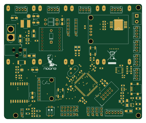 STM32
Noah hardware
GonzaCerv
120 × 100 mm122 parts2LMIT28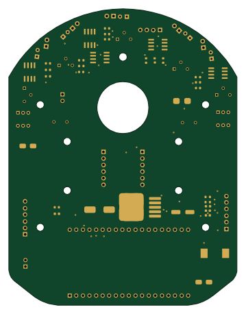 ESP32
Micromouse
Ojasp21
88 × 114.3 mm61 parts2LNo license8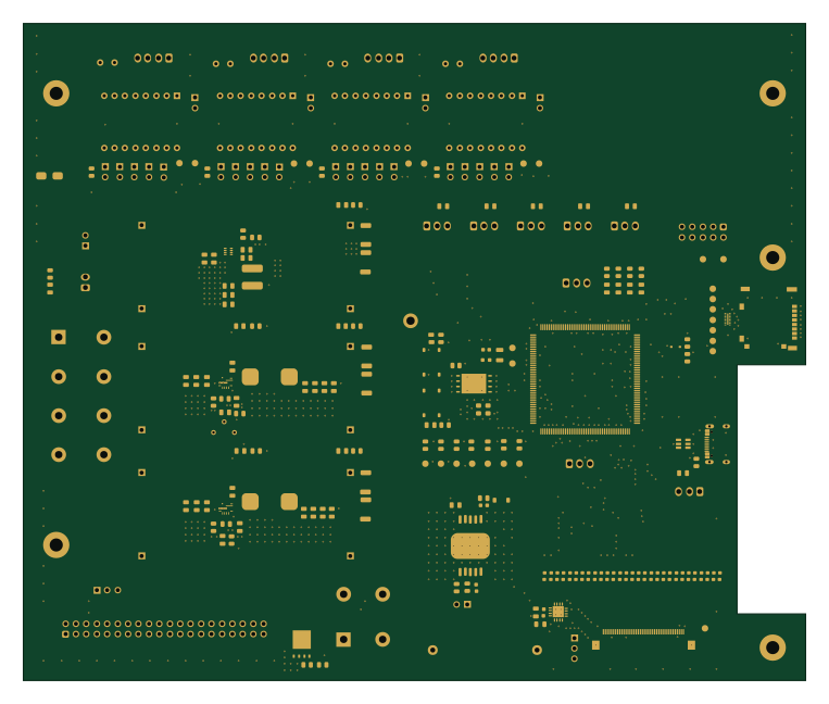 STM32
Topiary-TrimBot
griffinross2
190.5 × 160 mm251 parts4LGPL-3.02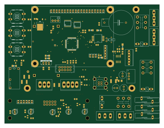 PIC
Test platform
kwiecinski
143.5 × 110.2 mm151 parts2LMIT2- schematic only · 27 partsESP32
Sata psu
majabojarska
27 partsMIT2 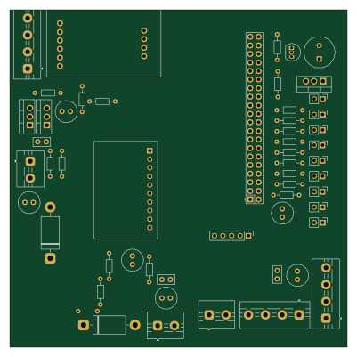 Raspberry Pi
BalancaSmart pannelsForExport
n0cturnes
100 × 100 mm54 parts2LNo license1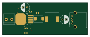
Buck converter
hasanberkdasar
77.1 × 29.7 mm11 parts2LMIT1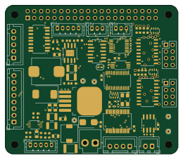
Moxl
perryc
65 × 56 mm88 parts6LApache-2.00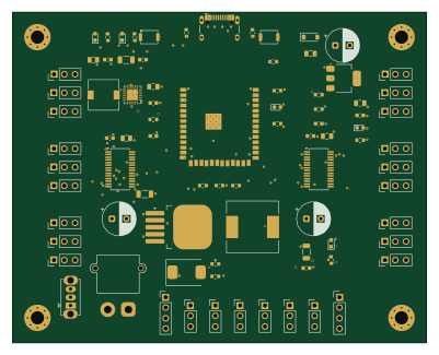 ESP32
Hexapod Robot Board
EnejiOhieku
100 × 80 mm64 parts4LNo license0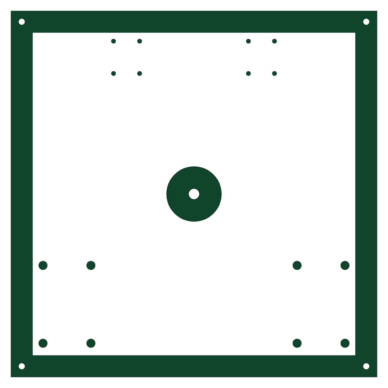
Capstone1
Wake-Up-It-s-a-Hospital
340 × 340 mm37 parts2LNo license0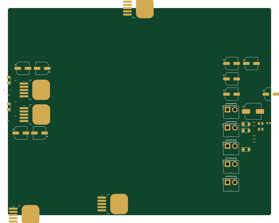
3levelstepDown
AVSRAVITEJA
139.6 × 109.9 mm35 parts2LNo license0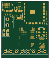 ESP32
Car-Neopixel-Board
M0HID
41.7 × 50 mm33 parts2LNo license0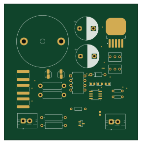
Adjustable-DC-DC-Buck-Converter
bharat-ops77
72 × 73.5 mm29 parts2LGPL-3.00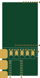 AVR/Arduino
ChessRobotArm
BujoreanuVlad
40.3 × 82.5 mm12 parts2LNo license0- schematic only · 54 partsRP2040/RP2350
SmartCellAnalyzer
asithniwantha
54 partsMIT0 - schematic only · 22 parts
Automated greenhouse
topnie
22 partsNo license0 - schematic only · 15 parts
Just making the drone
Jakefeldmanstarosta
15 partsNo license0 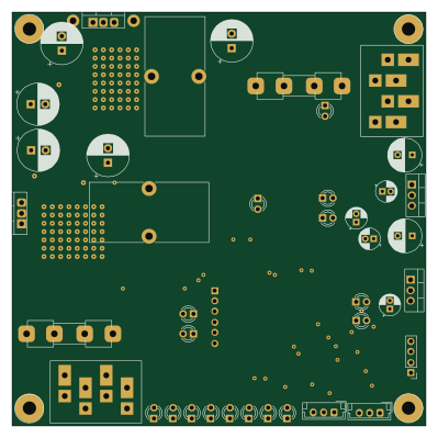 PIC
Bidirectional Power Converter 24V-12V with BMS
99.5 × 99.5 mm156 parts2LMIT3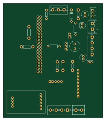
BalancaSmart
87.5 × 100 mm26 parts2LNo license1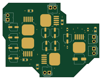
3levelstepDownIter2
83 × 63.5 mm35 parts2LNo license0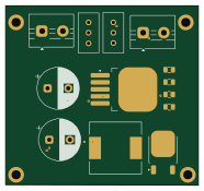
Xl4015-buck converter
cubistmind
46.5 × 43.5 mm13 parts2LNo license0
How designs wire the XL4015
Read from the KiCad layouts of 15 open source designs, one per repository: what each pin of the XL4015 connects to, and the resistors, capacitors and other passives placed on it.
- The FB pin has a resistor to GND on 8 of 14 designs, most often 1 kΩ (then 240 Ω).
- The SW pin has a inductor on 8 of 14 designs, most often 47 µH (then 40 µH).
- The VIN pin has a decoupling capacitor on 7 of 10 designs, most often 56 µF (then 1 mF).
| Pin | Connected to | Parts on the pin |
|---|---|---|
| GNDpin 1 | Connected to: GND 71% · a signal 21% | — |
| FBpin 2 | Connected to: Signal 86% |
|
| SWpin 3 | Connected to: Signal 79% |
|
| VINpin 5 | Connected to: 12V 50% · a signal 50% |
|
1 more pin varies from design to design. Connections count pins, parts count designs; values in brackets are how many parts had that value. Designs read include Noah hardware by GonzaCerv, Micromouse by Ojasp21, Bidirectional Power Converter 24V-12V with BMS by kwiecinski and Topiary-TrimBot by griffinross2.
The XL4015 in open source designs
The gallery holds 21 open source boards using the XL4015 from 19 GitHub repositories; a typical one measures about 88 × 99.5 mm and carries around 35 components.
82% are two-layer designs, the rest use four layers or more, and 43% carry an open source license.
The most starred is Noah hardware by GonzaCerv.
Parts used alongside the XL4015
Microcontrollers on boards using the XL4015
What boards using the XL4015 are built for
XL4015: common questions
Where can I find a XL4015 reference design?
Each of the 21 boards on this page is a real design using the XL4015. Open one to see how it is wired up, with the full BOM, a render of the layout and links to its KiCad files.
What resistor goes on the XL4015 FB pin?
The FB pin has a resistor to GND on 8 of 14 designs, most often 1 kΩ (then 240 Ω). Counted from the KiCad layouts of 15 open source designs using the XL4015.
How is the XL4015 SW pin connected?
The SW pin has a inductor on 8 of 14 designs, most often 47 µH (then 40 µH). Counted from the KiCad layouts of 15 open source designs using the XL4015.
What decoupling capacitors do designs use on the XL4015 VIN pin?
The VIN pin has a decoupling capacitor on 7 of 10 designs, most often 56 µF (then 1 mF). Counted from the KiCad layouts of 15 open source designs using the XL4015.
What parts are used alongside the XL4015?
The AMS1117-3.3, LM358 and PCA9685PW appear in the most repositories here.
Which microcontrollers do boards using the XL4015 use?
Most are built on ESP32 (4), PIC (2), STM32 (2) and AVR/Arduino (1).
How big is a typical board using the XL4015?
The median is 88 × 99.5 mm, and 82% are two-layer designs.
What is the most popular open source board using the XL4015?
By GitHub stars, Noah hardware by GonzaCerv, with 28 stars.
Can I simulate one of these boards using the XL4015 before building it?
Yes. HardLabs turns a board's netlist and BOM into a working simulation, so you can boot and test firmware against it with no hardware on your desk.