
B.C.I.-Design

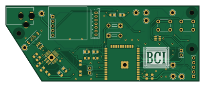
About the B.C.I.-Design PCB
B.C.I.-Design is an open source ESP32 PCB design by BMiller8008, published on GitHub. It is a 2-layer board measuring 105 × 41 mm, with 62 components from 41 distinct parts.
Its main chip is the ESP32-WROOM-32E, from the ESP32 family. Other key parts include the CP2102N-Axx-xQFN28 and USBLC6-2SC6. By type, the board carries 20 resistors, 9 test points, 9 capacitors, 7 diodes, 4 connectors and 3 ICs.
From the project
Purde ECE477 Senior Design
This is an example schematic from Ben Miller's Senior Design Team.
The board uses an ESP32, CP2102N usb-uart bridge, and a Pololu Buck Converter
I recomend using a EXTERNAL BRIDGE - to reduce complexity if hand soldering
You also could use a LDO rather than a buck converter, but the buck will be more power efficient
Main components on the B.C.I.-Design
B.C.I.-Design bill of materials (BOM)
62 components, 41 distinct parts.
| Qty | Part | Footprint | Refs |
|---|---|---|---|
| 1 | ESP32-WROOM-32E | ESP32-WROOM-32D | U1 |
| 1 | CP2102N-Axx-xQFN28 | QFN-28-1EP_5x5mm_P0.5mm_EP3.35x3.35mm | U2 |
| 1 | USBLC6-2SC6 | SOT-23-6 | U3 |
| 2 | SS8050-G | SOT-23 | Q1, Q2 |
| 1 | USB_B_Micro | USB_Micro-B_Wuerth_614105150721_Vertical | J1 |
| 1 | Barrel_Jack | BarrelJack_Wuerth_6941xx301002 | J2 |
| 1 | OLED JST PH 7pin | JST_PH_B7B-PH-K_1x07_P2.00mm_Vertical | J3 |
| 1 | D30V30F3 | PinHeader_1x05_P2.54mm_Vertical | J7 |
| 1 | Button 1 | SW_PUSH_6mm_H13mm | B1 |
| 1 | Button 2 | SW_PUSH_6mm_H13mm | B2 |
| 1 | Boot Button | SW_PUSH_1P1T_6x3.5mm_H4.3_APEM_MJTP1243 | Boot1 |
| 1 | Debug Conn | PinHeader_1x02_P2.54mm_Vertical | Debug1 |
| 1 | Conn_01x05_Socket | PinHeader_1x05_P2.54mm_Vertical | Mic_Conn1 |
| 1 | RST Button | SW_PUSH_1P1T_6x3.5mm_H4.3_APEM_MJTP1243 | RST1 |
| 1 | Bat TestPoint | TestPoint_Keystone_5010-5014_Multipurpose | TP1 |
| 1 | GND 1 | TestPoint_Keystone_5010-5014_Multipurpose | TP2 |
| 1 | GND 2 | TestPoint_Keystone_5010-5014_Multipurpose | TP3 |
| 1 | GND 3 | TestPoint_Keystone_5010-5014_Multipurpose | TP4 |
| 1 | ADC | TestPoint_Keystone_5010-5014_Multipurpose | TP5 |
| 2 | Power | TestPoint_Keystone_5010-5014_Multipurpose | TP6, TP9 |
Show 21 more
| Qty | Part | Footprint | Refs |
|---|---|---|---|
| 1 | Mic | TestPoint_Keystone_5010-5014_Multipurpose | TP7 |
| 1 | VUSB | TestPoint_Keystone_5010-5014_Multipurpose | TP8 |
| 1 | UART_Conn | PinHeader_1x02_P2.54mm_Vertical | UART1 |
| 1 | ESDA6V1BC6 | SOT-23-6 | D1 |
| 1 | Battery LED | LED_0805_2012Metric_Pad1.15x1.40mm_HandSolder | D4 |
| 1 | Power LED | LED_0805_2012Metric_Pad1.15x1.40mm_HandSolder | D5 |
| 1 | TX_LED | LED_0805_2012Metric_Pad1.15x1.40mm_HandSolder | D6 |
| 3 | RX_LED | LED_0805_2012Metric_Pad1.15x1.40mm_HandSolder | D7, D8, D9 |
| 1 | FerriteBead | L_0805_2012Metric_Pad1.05x1.20mm_HandSolder | FB1 |
| 2 | 10uF | C_0805_2012Metric_Pad1.18x1.45mm_HandSolder | C1, C5 |
| 6 | 0.1uF | C_0805_2012Metric_Pad1.18x1.45mm_HandSolder | C2, C3, C4, C6, C8, C9 |
| 1 | 22uF | C_0805_2012Metric_Pad1.18x1.45mm_HandSolder | C7 |
| 1 | 22.1K | R_0805_2012Metric_Pad1.20x1.40mm_HandSolder | R1 |
| 1 | 47.5k | R_0805_2012Metric_Pad1.20x1.40mm_HandSolder | R2 |
| 1 | 1k | R_0805_2012Metric_Pad1.20x1.40mm_HandSolder | R3 |
| 7 | 10k | R_0805_2012Metric_Pad1.20x1.40mm_HandSolder | R4, R8, R9, R10, R11, R12, R14 |
| 1 | 2k | R_0805_2012Metric_Pad1.20x1.40mm_HandSolder | R5 |
| 1 | 6M | R_0805_2012Metric_Pad1.20x1.40mm_HandSolder | R6 |
| 1 | 3M | R_0805_2012Metric_Pad1.20x1.40mm_HandSolder | R7 |
| 5 | 220 | R_0805_2012Metric_Pad1.20x1.40mm_HandSolder | R13, R15, R16, R17, R18 |
| 2 | 0 | R_0805_2012Metric_Pad1.20x1.40mm_HandSolder | R19, R20 |
B.C.I.-Design design files
The KiCad project lives in the BMiller8008/B.C.I.-Design repository on GitHub; these links point at the commit this page was built from.
B.C.I.-Design: common questions
What microcontroller does the B.C.I.-Design use?
The B.C.I.-Design is built around the ESP32-WROOM-32E, from the ESP32 family.
How big is the B.C.I.-Design PCB?
The B.C.I.-Design measures 105 × 41 mm, has 2 copper layers and is 1.6 mm thick.
How many components are on the B.C.I.-Design?
62 components, from 41 distinct parts. The full bill of materials is listed on this page.
Where can I download the B.C.I.-Design design files?
From the BMiller8008/B.C.I.-Design repository on GitHub, which has the KiCad layout and the schematic; the links under Design files point to each one.
Can I use the B.C.I.-Design design in my own project?
The repository has no license, so all rights stay with BMiller8008. Use it as a reference, and ask the author before reusing the design.
Can I test firmware for the B.C.I.-Design without the hardware?
Yes. HardLabs builds a simulation of the board from its netlist and BOM, so you can run and debug ESP32 firmware against it before you order a PCB.
Similar boards
 ESP32
ESP32Open Book Abridged Edition
joeycastillo
85 × 115 mm65 parts2LCC-BY-SA-4.08.1k ESP32
ESP32Badge
atopile
56.3 × 39 mm239 parts4LMIT4.0k ESP32
ESP32Esp32 minimal
36.2 × 26.8 mm20 parts2LMIT4.0k ESP32
ESP32Racer
StuckAtPrototype
36 × 50.2 mm70 parts4LApache-2.03.8k ESP32
ESP32Controller
29 × 74 mm58 parts4LApache-2.03.8k ESP32
ESP32Bitaxe
skot
56.5 × 99.8 mm86 parts4LCERN-OHL-S-2.01.4k