
PiPLC-Mainboard

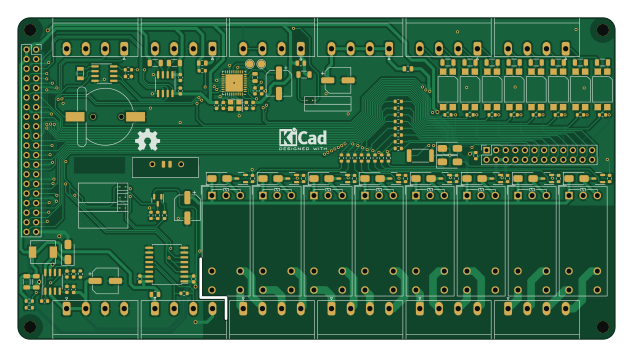
About the PiPLC-Mainboard PCB
PiPLC-Mainboard is an open source PCB design by Chrismettal, published on GitHub under the CC-BY-SA-4.0 license. It is a 2-layer board measuring 158 × 85 mm, with 144 components from 45 distinct parts.
Other key parts include the TPS54331D, NCN5121, ISO1540, EL817C and ISO3082DWR. By type, the board carries 54 resistors, 23 capacitors, 14 connectors, 13 ICs, 11 diodes and 9 transistors.
It belongs with the dev boards & breakouts designs in this gallery.
From the project
Glorified breakout board + DIN rail case for Pis
This is a Raspberry Pi breakout board + DIN rail case to use Pis in PLC-like industrial situations.
The design relies on a Raspberry Pi 4 for all functions to work. Pi 5 does also work but won't fit the 3D printed case, while Pi 3 and below don't allow for all functions to be used.
The PiPLC is intended to be used with Home Assistant, as well as OpenPLC. Obviously, since it's just a breakout board for any Pi, you can run whatever software you want, but Home Assistant and OpenPLC are the ones inspiring the design of this project.
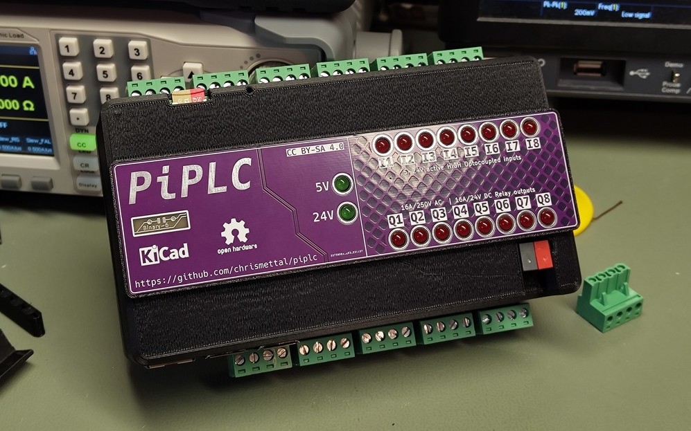
Main components on the PiPLC-Mainboard
PiPLC-Mainboard bill of materials (BOM)
144 components, 45 distinct parts — part numbers from the project's BOM.
| Qty | Part | Footprint | Refs |
|---|---|---|---|
| 1 | TPS54331D | SOIC-8_3.9x4.9mm_P1.27mm | U1 |
| 1 | NCN5121 | QFN-40-1EP_6x6mm_P0.5mm_EP4.6x4.6mm | U2 |
| 1 | ISO1540 | SOIC-8_3.9x4.9mm_P1.27mm | U3 |
| 8 | EL817C | Optocoupler_DIP_S1 | U4, U5, U6, U7, U8, U9, U10, U11 |
| 1 | ISO3082DWR | SOIC-16W_7.5x10.3mm_P1.27mm | U12 |
| 1 | PCF8523T | SOIC-8_3.9x4.9mm_P1.27mm | U13 |
| 8 | AO3400A | SOT-23-3 | Q1, Q2, Q3, Q4, Q5, Q6, Q7, Q8 |
| 1 | C8542 SS8550 Y2 | SOT-23 | Q9 |
| 1 | 32.768KHZ 32.768kHz | Crystal_SMD_3215-2Pin_3.2x1.5mm | Y1 |
| 1 | 16MHZ 16MHz | Crystal_SMD_3225-4Pin_3.2x2.5mm | Y2 |
| 12 | WJ2EDGRC-5.08-4P | PhoenixContact_MSTBA_2,5_4-G-5,08_1x04_P5.08mm_Horizontal | J1, J2, J3, J4, J5, J6, J7, J8 +4 |
| 1 | CONN_02X12_ODD_EVEN Conn_02x12_Odd_Even | PinSocket_2x12_P2.54mm_Vertical | J17 |
| 1 | Rpi GPIO | PinSocket_2x20_P2.54mm_Vertical | J99 |
| 1 | C70381 CR1220 (3V) | CR1220_Holder | BT1 |
| 4 | 500MA 500mA | Fuse_0805_2012Metric | F1, F2, F3, F4 |
| 1 | 1-Wire Pullup | SolderJumper-2_P1.3mm_Open_TrianglePad1.0x1.5mm | JP1 |
| 1 | AUTO_DE/NRE_2 Auto_DE/NRE_2 | SolderJumper-2_P1.3mm_Open_TrianglePad1.0x1.5mm | JP2 |
| 1 | AUTO_DE/NRE_1 Auto_DE/NRE_1 | SolderJumper-2_P1.3mm_Open_TrianglePad1.0x1.5mm | JP3 |
| 1 | GPIO23_DE/NRE | SolderJumper-2_P1.3mm_Open_TrianglePad1.0x1.5mm | JP4 |
| 8 | C2896748 G5RL-1A-E-TV8 DC24 | Relay_SPST_Omron_G2RL-1A-E_GroundMod | K1, K2, K3, K4, K5, K6, K7, K8 |
Show 25 more
| Qty | Part | Footprint | Refs |
|---|---|---|---|
| 1 | B340 | D_SMA | D1 |
| 9 | SS14 | D_SMA | D2, D12, D13, D14, D15, D16, D17, D18 +1 |
| 1 | SMAJ40CA | D_SMA | D3 |
| 1 | 6.8UH 6.8uH | Sunltech_SLO0630H | L1 |
| 3 | 10NF 10nF | C_0603_1608Metric | C1, C2, C3 |
| 1 | 4.7NF 4.7nF | C_0603_1608Metric | C4 |
| 1 | 33PF 33pF | C_0603_1608Metric | C5 |
| 2 | 47UF 47uF | C_1206_3216Metric | C6, C7 |
| 2 | 10PF 10pF | C_0603_1608Metric | C8, C9 |
| 1 | 220NF 220nF | C_0805_2012Metric | C10 |
| 1 | 47NF 47nF | C_0603_1608Metric | C11 |
| 7 | 100NF 100nF | C_0603_1608Metric | C12, C13, C14, C18, C19, C20, C21 |
| 4 | 100UF 100uF | CP_Elec_6.3x7.7 | C15, C16, C17, C22 |
| 1 | C23630 2.2µF | C_0603_1608Metric | C23 |
| 1 | 47K | R_0603_1608Metric | R1 |
| 11 | 10K | R_0603_1608Metric | R2, R24, R29, R32, R35, R38, R41, R44 +3 |
| 1 | 1.8K 1.8k | R_0603_1608Metric | R3 |
| 11 | 4K7 | R_1206_3216Metric | R4, R6, R7, R8, R9, R10, R11, R12 +3 |
| 1 | 27R | R_2512_6332Metric | R5 |
| 17 | 1K2 | R_0603_1608Metric | R16, R17, R18, R19, R20, R21, R22, R23 +9 |
| 8 | 100R | R_0603_1608Metric | R26, R28, R31, R34, R37, R40, R43, R46 |
| 1 | 1.5K 15k | R_0603_1608Metric | R45 |
| 1 | 10K 100K | R_0603_1608Metric | R49 |
| 1 | 120R | R_0603_1608Metric | R51 |
| 1 | 7K5 | R_0603_1608Metric | R54 |
PiPLC-Mainboard design files
The KiCad project lives in the Chrismettal/PiPLC repository on GitHub; these links point at the commit this page was built from.
PiPLC-Mainboard: common questions
How big is the PiPLC-Mainboard PCB?
The PiPLC-Mainboard measures 158 × 85 mm, has 2 copper layers and is 1.6 mm thick.
How many components are on the PiPLC-Mainboard?
144 components, from 45 distinct parts, with part numbers taken from the project's own BOM. The full bill of materials is listed on this page.
Where can I download the PiPLC-Mainboard design files?
From the Chrismettal/PiPLC repository on GitHub, which has the KiCad layout, the schematic and the BOM; the links under Design files point to each one.
Can I use the PiPLC-Mainboard design in my own project?
Yes, under the terms of its CC-BY-SA-4.0 license, which Chrismettal chose for the repository.
More boards in PiPLC
Similar boards

Radioberry juice
pa3gsb
65 × 56 mm87 parts2LNo license675
Radioberry preamp
65 × 56 mm137 parts2LNo license675
Hat
65 × 56 mm81 parts2LNo license675
Sram dev board
Wren6991
50 × 50 mm12 parts2LNo license508
ESP32
66.4 × 48.1 mm20 parts2LCC-BY-SA-4.0446
ESP32
66.4 × 48.1 mm20 parts2LCC-BY-SA-4.0446