
Smarthomepcb2logic

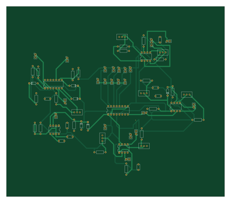
About the Smarthomepcb2logic PCB
Smarthomepcb2logic is an open source PCB design by chromyx, published on GitHub. It is a 2-layer board measuring 196.9 × 171.5 mm, with 69 components from 19 distinct parts.
Other key parts include the LM393, LM324, ULN2003 and NE555P. By type, the board carries 21 connectors, 20 resistors, 8 capacitors, 6 ICs and 6 diodes.
It belongs with the iot & wireless and sensors designs in this gallery.
From the project
The Analog Smart Environment Monitor is a multi-sensor safety and automation system designed to continuously monitor environmental conditions and respond automatically to critical events.
The Analog Smart Environment Monitor is a multi-sensor safety and automation system designed to continuously monitor environmental conditions and respond automatically to critical events.
Unlike modern IoT solutions that rely on microcontrollers and embedded software, this project operates entirely through analog signal processing, comparator networks, diode logic, and hardware-based decision making.
Main components on the Smarthomepcb2logic
Smarthomepcb2logic bill of materials (BOM)
69 components, 19 distinct parts.
| Qty | Part | Footprint | Refs |
|---|---|---|---|
| 3 | LM393 | DIP-8_W7.62mm | U1, U2, U4 |
| 1 | LM324 | DIP-14_W7.62mm | U3 |
| 1 | ULN2003 | DIP-16_W7.62mm | U5 |
| 1 | NE555P | DIP-8_W7.62mm | U6 |
| 1 | PWR_12V_IN | PinHeader_1x02_P2.54mm_Vertical | J1 |
| 1 | PWR_5V_IN | PinHeader_1x02_P2.54mm_Vertical | J2 |
| 1 | FLAME_SENSOR | PinHeader_1x02_P2.54mm_Vertical | J3 |
| 1 | MQ2_GAS | PinHeader_1x02_P2.54mm_Vertical | J4 |
| 16 | Conn_01x02 | PinHeader_1x02_P2.54mm_Vertical | J5, J7, J8, J9, J10, J11, J12, J13 +8 |
| 1 | Conn_01x03 | PinHeader_1x03_P2.54mm_Vertical | J6 |
| 1 | BUZZER_OUT | PinHeader_1x02_P2.54mm_Vertical | J_BUZ1 |
| 5 | R_Potentiometer | Potentiometer_Bourns_3296W_Vertical | RV1, RV2, RV5, RV6, RV7 |
| 2 | 10k | Potentiometer_Bourns_3296W_Vertical | RV3, RV4 |
| 6 | 1N4148 | D_DO-35_SOD27_P7.62mm_Horizontal | D1, D2, D3, D4, D5, D6 |
| 6 | 100nF | C_Disc_D5.0mm_W2.5mm_P5.00mm | C1, C2, C3, C4, C5, C9 |
| 1 | 47nF | C_Disc_D5.0mm_W2.5mm_P5.00mm | C7 |
| 1 | 10nF | C_Disc_D5.0mm_W2.5mm_P5.00mm | C8 |
| 19 | 10K | R_Axial_DIN0207_L6.3mm_D2.5mm_P10.16mm_Horizontal | R2(TD)1, R3(TD)1, R5(PU)1, R7, R8, R9(TH)1, R10(PU)1, R11(PU)1 +11 |
| 1 | R | R_Axial_DIN0207_L6.3mm_D2.5mm_P10.16mm_Horizontal | R23 |
Smarthomepcb2logic design files
The KiCad project lives in the chromyx/Analog-Home-Design repository on GitHub; these links point at the commit this page was built from.
Smarthomepcb2logic: common questions
How big is the Smarthomepcb2logic PCB?
The Smarthomepcb2logic measures 196.9 × 171.5 mm, has 2 copper layers and is 1.6 mm thick.
How many components are on the Smarthomepcb2logic?
69 components, from 19 distinct parts. The full bill of materials is listed on this page.
Where can I download the Smarthomepcb2logic design files?
From the chromyx/Analog-Home-Design repository on GitHub, which has the KiCad layout and the schematic; the links under Design files point to each one.
Can I use the Smarthomepcb2logic design in my own project?
The repository has no license, so all rights stay with chromyx. Use it as a reference, and ask the author before reusing the design.
More boards in Analog-Home-Design
Similar boards
Sensor smd
scottbez1
40 × 20 mm5 parts2LApache-2.04.2k
Sensors
StuckAtPrototype
15.2 × 9 mm14 parts4LApache-2.03.8k
EinkPDA screen
TalismanDesign
95 × 54 mm27 parts2LApache-2.02.0k
Microphone
Mentra-Community
5.5 × 6.1 mm6 parts2LMIT1.2k
TemperaturePCB PANEL
stuartpittaway
116 × 75.5 mm178 parts2LCC-BY-NC-4.01.1k
RPi RM0 WiFi/Bluetooth Module
schlae
11.1 × 14 mm76 parts6LNo license1.0k