
Lock in amplifier

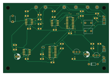
About the Lock in amplifier PCB
Lock in amplifier is an open source PCB design by cLLeB, published on GitHub. It is a 2-layer board measuring 90 × 60 mm, with 50 components from 31 distinct parts.
Other key parts include the MCP6022, LP2950-5.0, 74HC4053 and 74HC4060. By type, the board carries 17 resistors, 14 capacitors, 6 ICs, 6 test points, 3 connectors and 2 diodes.
It belongs with the audio designs in this gallery.
From the project
Optical lock-in amplifier for photodiode sensing: LTspice and ngspice simulation, KiCad board, built and measured
A complete optical lock-in amplifier, designed, simulated, laid out, assembled and tested by me in October 2026. An LED blinks at 1,024 Hz, a BPW34 photodiode picks up that light together with much stronger room light and lamp flicker, and the circuit outputs a DC voltage that follows only the light blinking in step with the LED.
1. Transimpedance amplifier. 100 kΩ and 100 pF turn photodiode current into voltage, with a 15.9 kHz bandwidth. 2. High pass filter and gain. A 159 Hz corner blocks the ambient DC and halves 100 Hz flicker, then a gain of 11. More gain would clip the flicker against…
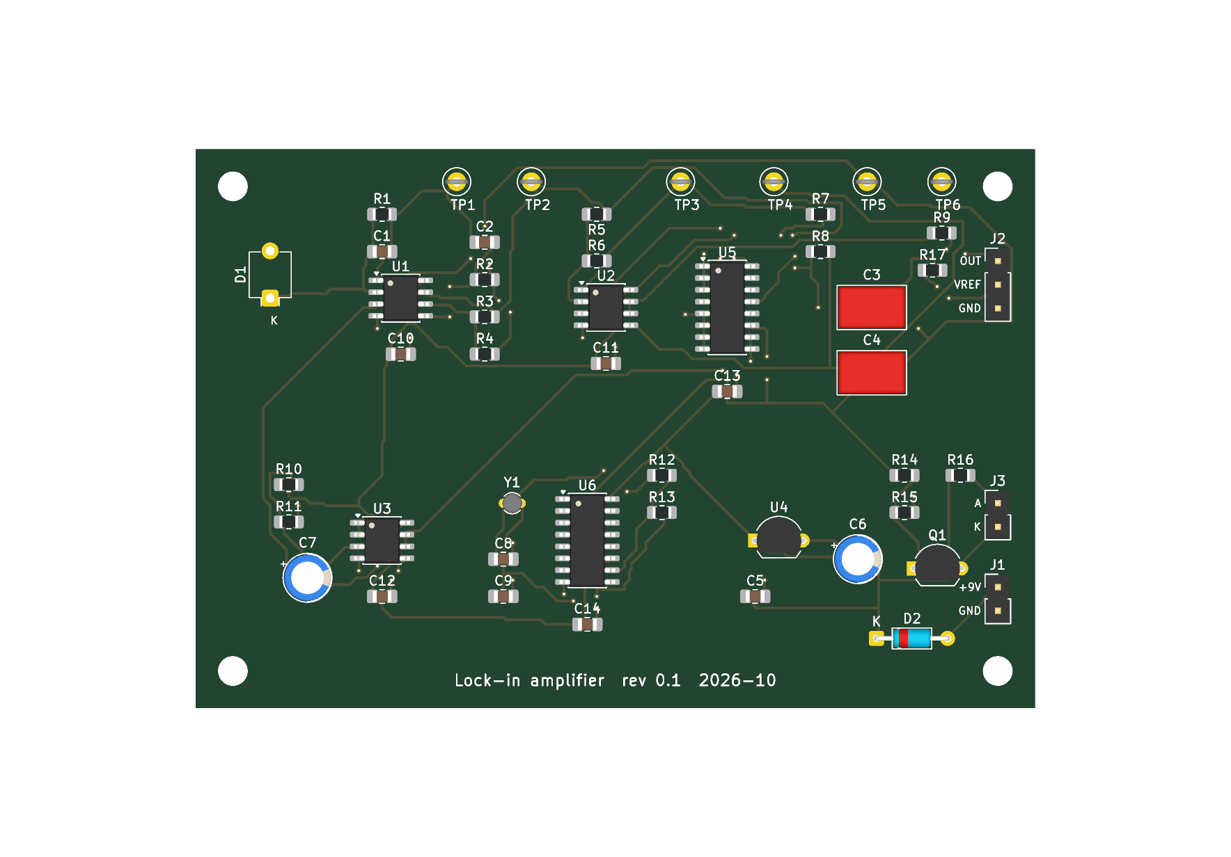
Main components on the Lock in amplifier
Lock in amplifier bill of materials (BOM)
50 components, 31 distinct parts — part numbers from the project's BOM.
| Qty | Part | Footprint | Refs |
|---|---|---|---|
| 3 | MCP6022 | SOIC-8_3.9x4.9mm_P1.27mm | U1, U2, U3 |
| 1 | LP2950-5.0 | TO-92_Inline_Wide | U4 |
| 1 | 74HC4053 | SOIC-16_3.9x9.9mm_P1.27mm | U5 |
| 1 | 74HC4060 | SOIC-16_3.9x9.9mm_P1.27mm | U6 |
| 1 | 2N7000 | TO-92_Inline_Wide | Q1 |
| 1 | 32.768k | Crystal_C26-LF_D2.1mm_L6.5mm_Vertical | Y1 |
| 1 | 9 V battery | PinHeader_1x02_P2.54mm_Vertical | J1 |
| 1 | OUT / VREF / GND | PinHeader_1x03_P2.54mm_Vertical | J2 |
| 1 | LED anode / cathode | PinHeader_1x02_P2.54mm_Vertical | J3 |
| 1 | TIA | TestPoint_Loop_D2.50mm_Drill1.0mm | TP1 |
| 1 | AC | TestPoint_Loop_D2.50mm_Drill1.0mm | TP2 |
| 1 | DEM | TestPoint_Loop_D2.50mm_Drill1.0mm | TP3 |
| 1 | REF | TestPoint_Loop_D2.50mm_Drill1.0mm | TP4 |
| 1 | VREF | TestPoint_Loop_D2.50mm_Drill1.0mm | TP5 |
| 1 | GND | TestPoint_Loop_D2.50mm_Drill1.0mm | TP6 |
| 1 | BPW34 | Osram_DIL2_4.3x4.65mm_P5.08mm | D1 |
| 1 | 1N4148 | D_DO-35_SOD27_P7.62mm_Horizontal | D2 |
| 1 | 100p | C_0805_2012Metric_Pad1.18x1.45mm_HandSolder | C1 |
| 1 | 10n | C_0805_2012Metric_Pad1.18x1.45mm_HandSolder | C2 |
| 2 | 1u film | C_Rect_L7.2mm_W4.5mm_P5.00mm_FKS2_FKP2_MKS2_MKP2 | C3, C4 |
Show 11 more
| Qty | Part | Footprint | Refs |
|---|---|---|---|
| 1 | 1u | C_0805_2012Metric_Pad1.18x1.45mm_HandSolder | C5 |
| 2 | 10u | CP_Radial_D5.0mm_P2.00mm | C6, C7 |
| 2 | 22p | C_0805_2012Metric_Pad1.18x1.45mm_HandSolder | C8, C9 |
| 5 | 100n | C_0805_2012Metric_Pad1.18x1.45mm_HandSolder | C10, C11, C12, C13, C14 |
| 5 | 100k | R_0805_2012Metric_Pad1.20x1.40mm_HandSolder | R1, R2, R7, R8, R15 |
| 5 | 10k | R_0805_2012Metric_Pad1.20x1.40mm_HandSolder | R3, R5, R6, R10, R11 |
| 1 | 1k | R_0805_2012Metric_Pad1.20x1.40mm_HandSolder | R4 |
| 3 | 100 | R_0805_2012Metric_Pad1.20x1.40mm_HandSolder | R9, R14, R17 |
| 1 | 330k | R_0805_2012Metric_Pad1.20x1.40mm_HandSolder | R12 |
| 1 | 10M | R_0805_2012Metric_Pad1.20x1.40mm_HandSolder | R13 |
| 1 | 680 | R_0805_2012Metric_Pad1.20x1.40mm_HandSolder | R16 |
Lock in amplifier design files
The KiCad project lives in the cLLeB/lock-in-amplifier repository on GitHub; these links point at the commit this page was built from.
- Layoutkicad/lockin.kicad_pcb
- Schematickicad/lockin.kicad_sch
- BOMkicad/bom.csv
Lock in amplifier: common questions
How big is the Lock in amplifier PCB?
The Lock in amplifier measures 90 × 60 mm, has 2 copper layers and is 1.6 mm thick.
How many components are on the Lock in amplifier?
50 components, from 31 distinct parts, with part numbers taken from the project's own BOM. The full bill of materials is listed on this page.
Where can I download the Lock in amplifier design files?
From the cLLeB/lock-in-amplifier repository on GitHub, which has the KiCad layout, the schematic and the BOM; the links under Design files point to each one.
Can I use the Lock in amplifier design in my own project?
The repository has no license, so all rights stay with cLLeB. Use it as a reference, and ask the author before reusing the design.
Similar boards
KLOR
GEIGEIGEIST
160.2 × 118.3 mm79 parts2LGPL-3.01.2k
ButtonsLEDs
shanteacontrols
390 × 37 mm82 parts2LApache-2.0956
USB
52 × 12.6 mm6 parts2LApache-2.0956
Pots
390 × 93 mm75 parts2LApache-2.0956
PicoGUS Hand386
polpo
29.2 × 75.2 mm43 parts4LGPL-2.0800
Snark barker
schlae
231.1 × 106.7 mm193 parts2LNo license687