
Pico serial

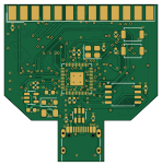
About the Pico serial PCB
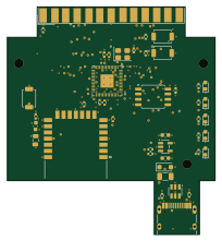
Pico serial is an open source RP2040/RP2350 PCB design by D-Modem, published on GitHub. It is a 4-layer board measuring 37 × 38 mm, with 69 components from 47 distinct parts.
Its main chip is the RP2040, from the RP2040/RP2350 family. Other key parts include the W25Q128JVS, AP2112K-3.3, USBLC6-2SC6, SP3238EEA and MAX3243EIDBR. By type, the board carries 30 capacitors, 20 resistors, 7 diodes, 6 ICs, 2 connectors and 2 switches.
From the project
Open source hardware modem designs. Supported by the D-Modem suite
netlist/buildnetlist.py` defines all parts and all connections on the board. The scripts make the netlist, the readable net list, the JLC parts list, the schematic and the PCB from it. Thus, change the script, not the outputs.
The script makes these boards: - The hood board (the default). It fits in a standard DB25 hood. - pico-serial W (--variant w, SPEC-W.md). It adds an RM2 Bluetooth module, and it is in a 3D-printed hood (enclosure/). Its files have a -w suffix. See pico-serial W. - pico-serial Line (--variant line, SPEC-L.md). It is a different device on the same RP2040 core: a USB-C…
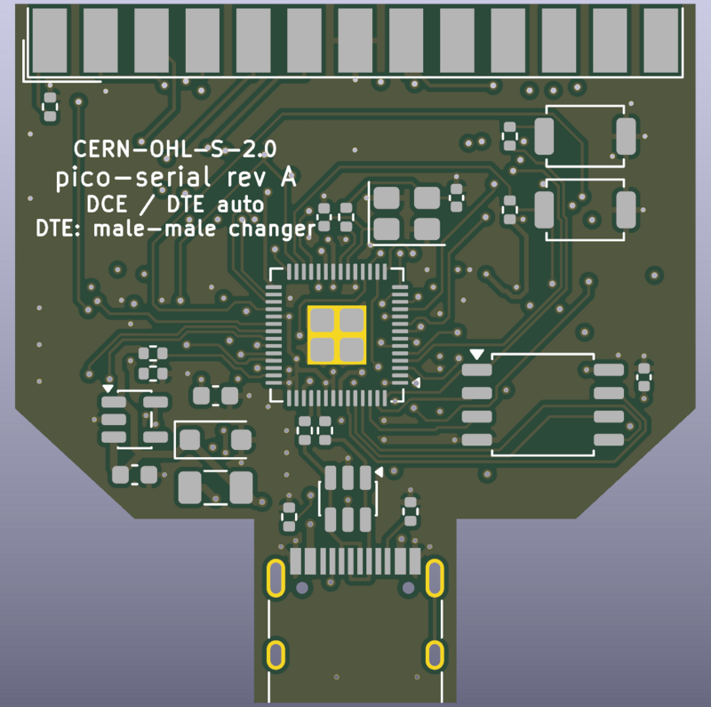
Main components on the Pico serial
Pico serial bill of materials (BOM)
69 components, 47 distinct parts — part numbers from the project's BOM.
| Qty | Part | Footprint | Refs |
|---|---|---|---|
| 1 | RP2040 | QFN-56-1EP_7x7mm_P0.4mm_EP3.2x3.2mm | U1 |
| 1 | W25Q128JVS | SOIC-8_5.3x5.3mm_P1.27mm | U2 |
| 1 | AP2112K-3.3 | SOT-23-5 | U3 |
| 1 | USBLC6-2SC6 | SOT-23-6 | U4 |
| 1 | SP3238EEA | SSOP-28_5.3x10.2mm_P0.65mm | U5 |
| 1 | MAX3243EIDBR | SSOP-28_5.3x10.2mm_P0.65mm | U6 |
| 1 | 12MHZ 12MHz | Crystal_SMD_3225-4Pin_3.2x2.5mm | Y1 |
| 1 | C165948 USB_C | USB_C_Receptacle_HRO_TYPE-C-31-M-12 | J1 |
| 1 | DB25_Female | DSUB-25_Socket_EdgeMount_P2.77mm | J2 |
| 1 | 0.5A | Fuse_1206_3216Metric | F1 |
| 1 | C720477 BOOTSEL | SW_SPST_TS-1088-xR020 | SW1 |
| 1 | C720477 RESET | SW_SPST_TS-1088-xR020 | SW2 |
| 1 | SMF5.0A | D_SOD-123F | D1 |
| 1 | BZT52C43 LED_PWR | LED_0603_1608Metric | D2 |
| 1 | MMBD3004S LED_TR | LED_0603_1608Metric | D3 |
| 1 | MMBD3004S LED_CD | LED_0603_1608Metric | D4 |
| 1 | C2286 LED_SD | LED_0603_1608Metric | D5 |
| 1 | C2286 LED_RD | LED_0603_1608Metric | D6 |
| 1 | LED_RI | LED_0603_1608Metric | D7 |
| 1 | 4.7NF 4.7nF | C_0402_1005Metric | C1 |
Show 27 more
| Qty | Part | Footprint | Refs |
|---|---|---|---|
| 2 | 10UF 10uF | C_0603_1608Metric | C2, C3 |
| 12 | 100NF 100nF | C_0402_1005Metric | C4, C5, C6, C7, C8, C9, C10, C11 +4 |
| 2 | 1UF 1uF | C_0402_1005Metric | C12, C13 |
| 2 | 15PF 15pF | C_0402_1005Metric | C16, C17 |
| 2 | 100NF 220nF | C_0402_1005Metric | C19, C25 |
| 1 | 100NF 1uF | C_0603_1608Metric | C20 |
| 2 | C2915768 1uF | C_0603_1608Metric | C21, C22 |
| 1 | C28323 1uF | C_0402_1005Metric | C23 |
| 1 | 2.7NF 1uF | C_0603_1608Metric | C26 |
| 1 | 10NF 1uF | C_0603_1608Metric | C27 |
| 1 | C106841 1uF | C_0603_1608Metric | C28 |
| 1 | C524545 1uF | C_0402_1005Metric | C29 |
| 1 | C524545 100nF | C_0402_1005Metric | C30 |
| 2 | 5.1K 5.1k | R_0402_1005Metric | R1, R2 |
| 1 | 1M | R_0402_1005Metric | R3 |
| 2 | 100K 100k | R_0402_1005Metric | R4, R5 |
| 2 | 27R | R_0402_1005Metric | R6, R7 |
| 3 | 1k | R_0402_1005Metric | R8, R9, R17 |
| 1 | 10K 10k | R_0402_1005Metric | R10 |
| 1 | 4.7K 0R | R_0402_1005Metric | R11 |
| 2 | 4.7K 100k | R_0402_1005Metric | R12, R13 |
| 1 | 56.2R 100k | R_0402_1005Metric | R14 |
| 1 | 56.2R 1k | R_0402_1005Metric | R15 |
| 1 | 1.07K 1k | R_0402_1005Metric | R16 |
| 1 | 536R 1k | R_0402_1005Metric | R18 |
| 1 | 3.65K 1k | R_0402_1005Metric | R19 |
| 1 | 150R 1k | R_0402_1005Metric | R20 |
Pico serial design files
The KiCad project lives in the D-Modem/hardware repository on GitHub; these links point at the commit this page was built from.
Pico serial: common questions
What microcontroller does the Pico serial use?
The Pico serial is built around the RP2040, from the RP2040/RP2350 family.
How big is the Pico serial PCB?
The Pico serial measures 37 × 38 mm, has 4 copper layers and is 1.6 mm thick.
How many components are on the Pico serial?
69 components, from 47 distinct parts, with part numbers taken from the project's own BOM. The full bill of materials is listed on this page.
Where can I download the Pico serial design files?
From the D-Modem/hardware repository on GitHub, which has the KiCad layout, the schematic and the BOM; the links under Design files point to each one.
Can I use the Pico serial design in my own project?
The repository has no license, so all rights stay with D-Modem. Use it as a reference, and ask the author before reusing the design.
Can I test firmware for the Pico serial without the hardware?
Yes. HardLabs builds a simulation of the board from its netlist and BOM, so you can run and debug RP2040/RP2350 firmware against it before you order a PCB.
More boards in hardware
Similar boards
 RP2040/RP2350
OSO-BOOK-C1
joeycastillo
85 × 115 mm29 parts2LCC-BY-SA-4.08.1k RP2040/RP2350
Corne cherry
foostan
277.2 × 107.5 mm164 parts2LCC-BY-4.07.7k RP2040/RP2350
Corne chocolate
277.2 × 107.5 mm164 parts2LCC-BY-4.07.7k RP2040/RP2350
Jitx design
gusmanb
55.5 × 65 mm26 parts4LGPL-3.05.0k RP2040/RP2350
LogicAnalyzer
57 × 55.2 mm6 parts2LGPL-3.05.0k RP2040/RP2350
Main
google
98 × 71 mm102 parts2LApache-2.02.9k