
Cross point exp brd mini red2-smd

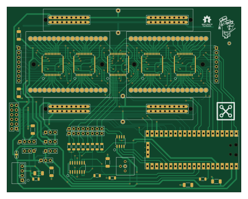
About the Cross point exp brd mini red2-smd PCB
Cross point exp brd mini red2-smd is an open source RP2040/RP2350 PCB design by damercer, published on GitHub under the CC-BY-SA-4.0 license. It is a 2-layer board measuring 127 × 100.3 mm, with 122 components from 29 distinct parts.
Its main chip is the Pico, from the RP2040/RP2350 family. Other key parts include the CH446DS1, AS3911B-AQFT, MCP4822 and MCP6004. By type, the board carries 76 connectors, 12 resistors, 8 ICs, 8 capacitors, 3 jumpers and 1 test point.
It belongs with the dev boards & breakouts designs in this gallery.
From the project
A Software Configurable Solderless Breadboard
The goal is to evaluate the educational benefits and potential drawbacks of these software-configured hardware systems compared to traditional manual wiring. By doing so, it addresses the need for balancing hands-on skills with error minimization and conceptual understanding in electrical engineering education. # Analog switch matrix cross point experiment breadboard. # Production PCB (Red3 version, instructions for ordering boards can be found in PCB Projects folder)
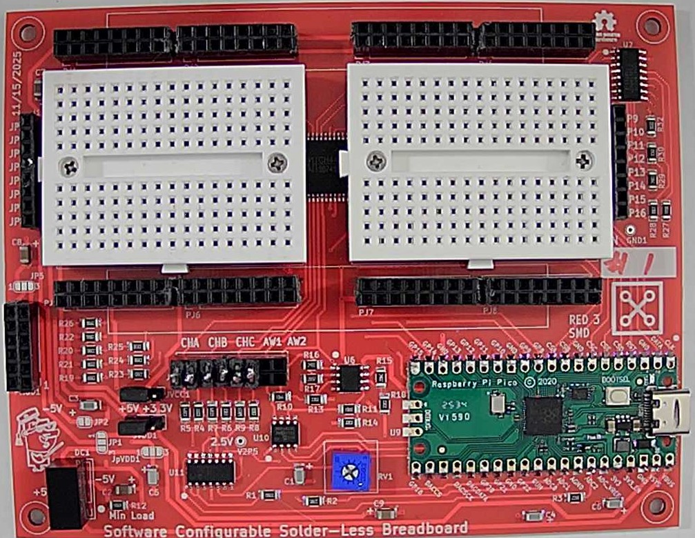
Main components on the Cross point exp brd mini red2-smd
Cross point exp brd mini red2-smd bill of materials (BOM)
122 components, 29 distinct parts — part numbers from the project's BOM.
| Qty | Part | Footprint | Refs |
|---|---|---|---|
| 4 | CH446DS1 | LQFP44_Tight | U1, U2, U4, U5 |
| 1 | AS3911B-AQFT CH446DS1 Austria Micro Systems | LQFP44_Tight | U3 |
| 1 | Pico | RPi_Pico_SMD_TH | U9 |
| 1 | MCP4822 | SO-8_3.9x4.9mm_P1.27mm | U10 |
| 1 | MCP6004 | SO-14_3.9x8.65mm_P1.27mm | U11 |
| 1 | 632723300011 Conn_01x08_Pin Wurth | PinHeader_1x08_P2.54mm_Vertical | J1 |
| 2 | Conn_01x08_Pin C&K | PinHeader_1x08_P2.54mm_Vertical | J2, J8 |
| 2 | Solderless_mini_2Rows-17Pins | Solderless_mini_mount_holes_2x17_P2.54mm | J3, J4 |
| 2 | 73412-0110 Solderless_power-4Pins Molex | Solderless_power_2x4_P2.54mm | J5, J6 |
| 1 | XF2M-3515-1A Conn_01x08_Pin Omron | PinHeader_1x08_P2.54mm_Vertical | J7 |
| 68 | POGO_PIN_01X01_70-9150 | MF_Connectors-POGO_PIN_70-9150 | PP1, PP2, PP3, PP4, PP5, PP6, PP7, PP8 +60 |
| 1 | CME0505S3C | PinHeader_1x04_P2.54mm_Vertical | DC1 |
| 1 | TestPoint | TestPoint_THTPad_D1.5mm_Drill0.7mm | GND1 |
| 4 | TestPoint | TestPoint_THTPad_D2.0mm_Drill1.0mm | GND2, VCC1, VDD1, VEE1 |
| 1 | SolderJumper_3_Open | SolderJumper-3_P1.3mm_Open_RoundedPad1.0x1.5mm_NumberLabels | JP1 |
| 2 | SolderJumper_2_Open | SolderJumper-2_P1.3mm_Open_RoundedPad1.0x1.5mm | JP3, JP4 |
| 1 | Conn_01x04_Pin | PinHeader_1x04_P2.54mm_Vertical | JVEE1 |
| 5 | Conn_01x03_Pin | PinHeader_1x03_P2.54mm_Vertical | JpVDD1, JpVDD2, JpVDD3, JpVDD4, JpVDD5 |
| 1 | Conn_02x06_Top_Bottom | PMOD_Header_2x06_P2.54mm | PMOD1 |
| 1 | 10k | Potentiometer_Bourns_3386P_Vertical | RV1 |
Show 9 more
| Qty | Part | Footprint | Refs |
|---|---|---|---|
| 1 | TestPoint | TestPoint_THTPad_D1.5mm_Drill0.7mm | TP6 |
| 7 | 0.22u | C_1808_4520Metric | C1, C3, C4, C5, C6, C7, C8 |
| 1 | 100PF 0.22u Various | C_1808_4520Metric | C2 |
| 3 | 330R 220 Various | R_1206_3216Metric | R1, R2, R3 |
| 3 | 330k | R_1206_3216Metric | R4, R6, R8 |
| 3 | 680k | R_1206_3216Metric | R5, R7, R9 |
| 1 | 33k | R_1206_3216Metric | R10 |
| 1 | 68k | R_1206_3216Metric | R11 |
| 1 | 510 | R_1206_3216Metric | R12 |
Cross point exp brd mini red2-smd design files
The KiCad project lives in the damercer/Cross-Point-Project repository on GitHub; these links point at the commit this page was built from.
Cross point exp brd mini red2-smd: common questions
What microcontroller does the Cross point exp brd mini red2-smd use?
The Cross point exp brd mini red2-smd is built around the Pico, from the RP2040/RP2350 family.
How big is the Cross point exp brd mini red2-smd PCB?
The Cross point exp brd mini red2-smd measures 127 × 100.3 mm, has 2 copper layers and is 1.6 mm thick.
How many components are on the Cross point exp brd mini red2-smd?
122 components, from 29 distinct parts, with part numbers taken from the project's own BOM. The full bill of materials is listed on this page.
Where can I download the Cross point exp brd mini red2-smd design files?
From the damercer/Cross-Point-Project repository on GitHub, which has the KiCad layout, the schematic and the BOM; the links under Design files point to each one.
Can I use the Cross point exp brd mini red2-smd design in my own project?
Yes, under the terms of its CC-BY-SA-4.0 license, which damercer chose for the repository.
Can I test firmware for the Cross point exp brd mini red2-smd without the hardware?
Yes. HardLabs builds a simulation of the board from its netlist and BOM, so you can run and debug RP2040/RP2350 firmware against it before you order a PCB.
More boards in Cross-Point-Project
 RP2040/RP2350
Cross point exp brd mini red2-sjmp
127 × 100.3 mm116 parts2LCC-BY-SA-4.03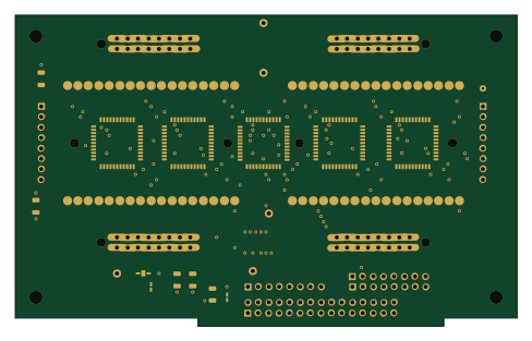
Cross point exp brd mini red2-m2k
121.9 × 75.6 mm96 parts2LCC-BY-SA-4.03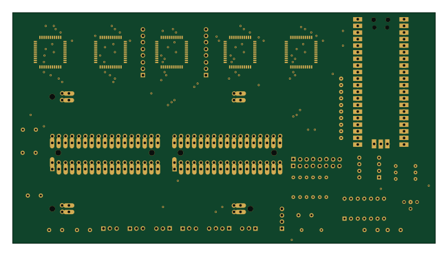 RP2040/RP2350
Cross point exp brd mini lc
162.6 × 88.9 mm57 parts2LCC-BY-SA-4.03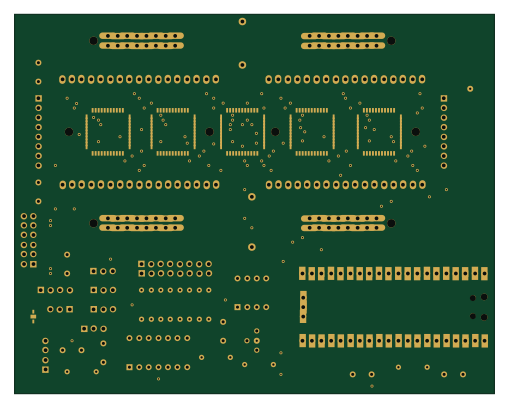 RP2040/RP2350
Cross point exp brd mini v2
127 × 100.3 mm54 parts2LCC-BY-SA-4.03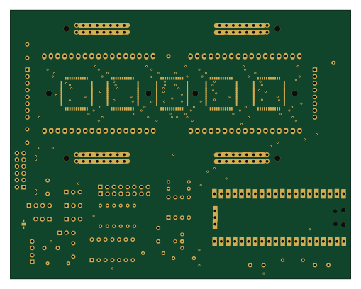 RP2040/RP2350
Cross point exp brd mini smd
127 × 100.3 mm51 parts2LCC-BY-SA-4.03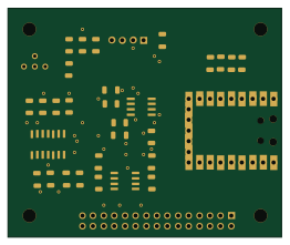 RP2040/RP2350
Pi mini zero adapter
65.4 × 54.6 mm33 parts2LCC-BY-SA-4.03
Similar boards
 RP2040/RP2350
Open Book Abridged Edition
joeycastillo
85 × 115 mm29 parts2LCC-BY-SA-4.08.1k RP2040/RP2350
Corne
foostan
277.2 × 107.5 mm164 parts2LCC-BY-4.07.7k RP2040/RP2350
Corne
277.2 × 107.5 mm164 parts2LCC-BY-4.07.7k RP2040/RP2350
Msa
Mentra-Community
47.8 × 9.4 mm53 parts2LMIT1.2k RP2040/RP2350
Open Source Smart Glasses
93 × 10.5 mm80 parts4LMIT1.2k RP2040/RP2350
MSA
30.5 × 138 mm61 parts2LMIT1.2k