
Pi mini zero adapter

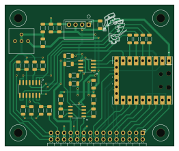
About the Pi mini zero adapter PCB
Pi mini zero adapter is an open source RP2040/RP2350 PCB design by damercer, published on GitHub under the CC-BY-SA-4.0 license. It is a 2-layer board measuring 65.4 × 54.6 mm, with 33 components from 18 distinct parts.
Its main chip is the Pico-mini-zero, from the RP2040/RP2350 family. Other key parts include the MCP6004T-I/SL, MCP4822-E/SN and MC33202DR2G. By type, the board carries 23 resistors, 4 ICs, 3 capacitors and 1 connector.
It belongs with the dev boards & breakouts designs in this gallery.
From the project
A Software Configurable Solderless Breadboard
The goal is to evaluate the educational benefits and potential drawbacks of these software-configured hardware systems compared to traditional manual wiring. By doing so, it addresses the need for balancing hands-on skills with error minimization and conceptual understanding in electrical engineering education. # Analog switch matrix cross point experiment breadboard. # Production PCB (Red3 version, instructions for ordering boards can be found in PCB Projects folder)
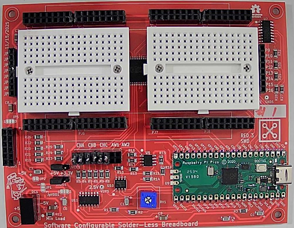
Main components on the Pi mini zero adapter
Pi mini zero adapter bill of materials (BOM)
33 components, 18 distinct parts — part numbers from the project's BOM.
| Qty | Part | Footprint | Refs |
|---|---|---|---|
| 1 | Pico-mini-zero | RPi_Mini_Zero_SMD_TH | U1 |
| 1 | MCP6004T-I/SL MCP6004 | SOIC-14_3.9x8.7mm_P1.27mm | U2 |
| 1 | MCP4822-E/SN MCP4822 | SOIC-8_3.9x4.9mm_P1.27mm | U3 |
| 1 | MC33202DR2G MCP6002-xSN | SO-8_3.9x4.9mm_P1.27mm | U4 |
| 1 | Conn_02x15_Odd_Even | PinHeader_2x15_P2.54mm_Horizontal | J1 |
| 1 | RFM-0505S | RFM-0505S | DC1 |
| 1 | 5k | Potentiometer_Bourns_3386P_Vertical | RV1 |
| 3 | 10UF 10uF | C_1206_3216Metric | C1, C2, C3 |
| 4 | 220 | R_1206_3216Metric | R1, R2, R3, R4 |
| 4 | 680k | R_1206_3216Metric | R5, R7, R9, R11 |
| 4 | 330k | R_1206_3216Metric | R6, R8, R10, R12 |
| 1 | 470 | R_1206_3216Metric | R13 |
| 2 | 3.9K 3.9k | R_1206_3216Metric | R14, R15 |
| 2 | 33K 33k | R_1206_3216Metric | R16, R17 |
| 2 | 24K 24k | R_1206_3216Metric | R18, R19 |
| 2 | 20K 20k | R_1206_3216Metric | R20, R21 |
| 1 | 120 | R_1206_3216Metric | R22 |
| 1 | 390 | R_1206_3216Metric | R23 |
Pi mini zero adapter design files
The KiCad project lives in the damercer/Cross-Point-Project repository on GitHub; these links point at the commit this page was built from.
Pi mini zero adapter: common questions
What microcontroller does the Pi mini zero adapter use?
The Pi mini zero adapter is built around the Pico-mini-zero, from the RP2040/RP2350 family.
How big is the Pi mini zero adapter PCB?
The Pi mini zero adapter measures 65.4 × 54.6 mm, has 2 copper layers and is 1.6 mm thick.
How many components are on the Pi mini zero adapter?
33 components, from 18 distinct parts, with part numbers taken from the project's own BOM. The full bill of materials is listed on this page.
Where can I download the Pi mini zero adapter design files?
From the damercer/Cross-Point-Project repository on GitHub, which has the KiCad layout, the schematic and the BOM; the links under Design files point to each one.
Can I use the Pi mini zero adapter design in my own project?
Yes, under the terms of its CC-BY-SA-4.0 license, which damercer chose for the repository.
Can I test firmware for the Pi mini zero adapter without the hardware?
Yes. HardLabs builds a simulation of the board from its netlist and BOM, so you can run and debug RP2040/RP2350 firmware against it before you order a PCB.
More boards in Cross-Point-Project
 RP2040/RP2350
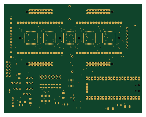
Cross point exp brd mini red2-smd
127 × 100.3 mm122 parts2LCC-BY-SA-4.03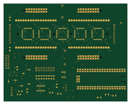 RP2040/RP2350
Cross point exp brd mini red2-sjmp
127 × 100.3 mm116 parts2LCC-BY-SA-4.03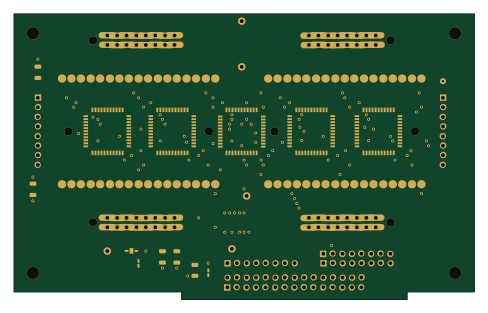
Cross point exp brd mini red2-m2k
121.9 × 75.6 mm96 parts2LCC-BY-SA-4.03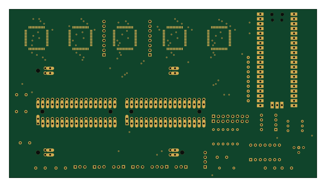 RP2040/RP2350
Cross point exp brd mini lc
162.6 × 88.9 mm57 parts2LCC-BY-SA-4.03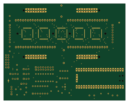 RP2040/RP2350
Cross point exp brd mini v2
127 × 100.3 mm54 parts2LCC-BY-SA-4.03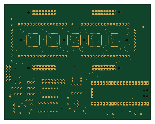 RP2040/RP2350
Cross point exp brd mini smd
127 × 100.3 mm51 parts2LCC-BY-SA-4.03
Similar boards
 RP2040/RP2350
Open Book Abridged Edition
joeycastillo
85 × 115 mm29 parts2LCC-BY-SA-4.08.1k RP2040/RP2350
Corne
foostan
277.2 × 107.5 mm164 parts2LCC-BY-4.07.7k RP2040/RP2350
Corne
277.2 × 107.5 mm164 parts2LCC-BY-4.07.7k RP2040/RP2350
LogicAnalyzer
gusmanb
57 × 55.2 mm6 parts2LGPL-3.05.0k RP2040/RP2350
Jitx design
55.5 × 65 mm26 parts4LGPL-3.05.0k RP2040/RP2350
Pro V2
kata0510
290.1 × 130 mm270 parts2LMIT2.3k