
Piezometer

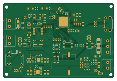
About the Piezometer PCB
Piezometer is an open source ESP32 PCB design by Daniele21211, published on GitHub. It is a 2-layer board measuring 99.7 × 66.9 mm, with 161 components from 93 distinct parts.
Its main chip is the DSPIC33EP256MC202-I/SO, from the ESP32 family. Other key parts include the ADR4525BRZ-R7, ADS1255IDBTG4, LT1764AEFE#TRPBF, LT1764AEFE-3.3 and LTM8074IY#PBF. By type, the board carries 77 capacitors, 46 resistors, 12 ICs, 11 diodes, 5 connectors and 3 crystals.
Main components on the Piezometer
Piezometer bill of materials (BOM)
161 components, 93 distinct parts — part numbers from the project's BOM.
| Qty | Part | Footprint | Refs |
|---|---|---|---|
| 1 | ADR4525BRZ-R7 | SOIC127P600X175-8N | IC1 |
| 1 | ADS1255IDBTG4 | SSOP-20_5.3x7.2mm_P0.65mm | IC2 |
| 1 | LT1764AEFE#TRPBF | SOP65P640X110-17N | IC4 |
| 1 | LT1764AEFE-3.3 | SOP65P640X110-17N | IC5 |
| 1 | LTM8074IY#PBF | BGA25C65P5X5_400X400X198 | IC7 |
| 1 | MCP79520-I/MS MCP79520-I_MS | SOP50P490X110-10N | IC8 |
| 1 | DSPIC33EP256MC202-I/SO ESP32-P4 | QFN-104_L10.0-W10.0-P0.35-TL-EP8.5-ESP32-P4 | U1 |
| 1 | MP2303ADN-LF-Z TLV62565DBVx | SOT-23-5 | U2 |
| 1 | EVAL-ADXL355Z SP3485CN | SOIC-8_3.9x4.9mm_P1.27mm | U3 |
| 1 | AMS1117-3.3 USB | HCTYPEC16PCB10 | U4 |
| 1 | W25Q128JVS | SOIC-8_5.3x5.3mm_P1.27mm | U5 |
| 1 | INA333xxDGK | VSSOP-8_3x3mm_P0.65mm | U7 |
| 1 | PBSS4240TVL | SOT-23-3 | Q1 |
| 1 | 7.68MHz | Crystal_SMD_ECS_CSM3X-2Pin_7.6x4.1mm | Y1 |
| 1 | X322526MEB4SC 40Mhz | X322540MPB4SI | Y3 |
| 1 | Crystal_GND23 | MC-306 | Y4 |
| 1 | 1725656 M12 | TerminalBlock_Phoenix_MKDS-1,5-2-5.08_1x02_P5.08mm_Horizontal | J1 |
| 1 | 1725656 Conn_01x03_Pin | TerminalBlock_Phoenix_MKDS-1,5-3-5.08_1x03_P5.08mm_Horizontal | J2 |
| 1 | PZ254V-11-06P Conn_01x02_Pin | CR12202 | J3 |
| 1 | 压力传感器 | TerminalBlock_Phoenix_MKDS-1,5-2-5.08_1x02_P5.08mm_Horizontal | J4 |
Show 73 more
| Qty | Part | Footprint | Refs |
|---|---|---|---|
| 1 | 电磁阀 | TerminalBlock_Phoenix_MKDS-1,5-2-5.08_1x02_P5.08mm_Horizontal | J5 |
| 1 | Relay_SPDT | Relay_SPDT_CUI_SR5 | K2 |
| 1 | 5GSH935 RESET | SW | SW1 |
| 1 | BOOT | SW | SW2 |
| 2 | 1N4148WS green | LED_0603_1608Metric | D1, D7 |
| 2 | SMBJ6.0CAQ-TP | DIONM5336X262N | D2, D3 |
| 1 | green | LED_0603_1608Metric | D4 |
| 2 | SS34 green | LED_0603_1608Metric | D5, D10 |
| 1 | B5819WSL-TP 3SMBJ5918B-TP | D_SMA | D6 |
| 1 | NCD0805R1 BYS10-45 | D_DO-41_SOD81_P10.16mm_Horizontal | D8 |
| 1 | NCD0805R1 green | LED_0603_1608Metric | D9 |
| 1 | SMAJ15A | DO-214AC | D11 |
| 1 | 22UH 2.2uH | L_Changjiang_FNR3015S | L1 |
| 1 | CRCW20100000Z0EF | L_1206_3216Metric | L2 |
| 1 | MPZ2012S221AT000 | L_1206_3216Metric | L3 |
| 1 | 1UF 10uF | C_1206_3216Metric | C1 |
| 2 | 22UF 0.1uF | C_0603_1608Metric | C2, C9 |
| 1 | 22UF 100pF | C_0603_1608Metric | C3 |
| 1 | 100NF 0.1uF | C_0603_1608Metric | C4 |
| 1 | 100NF 47uF | C_1206_3216Metric | C5 |
| 2 | 100NF 10uF | C_1206_3216Metric | C6, C12 |
| 2 | 100NF 22pF | C_0603_1608Metric | C7, C14 |
| 1 | 100NF 100pF | C_0603_1608Metric | C8 |
| 1 | 3.3NF 18pF | C_0603_1608Metric | C10 |
| 1 | 22UF 18pF | C_0603_1608Metric | C11 |
| 2 | 220UF 104 | C_0603_1608Metric | C13, C19 |
| 1 | 220UF 22pF | C_0603_1608Metric | C15 |
| 1 | 10NF 10uF | C_1206_3216Metric | C16 |
| 2 | 100NF 104 | C_0603_1608Metric | C17, C20 |
| 1 | 10NF 104 | C_0603_1608Metric | C18 |
| 7 | 10uF | C_1206_3216Metric | C21, C22, C30, C37, C65, C67, C88 |
| 16 | 104 | C_0603_1608Metric | C23, C24, C25, C26, C27, C29, C31, C32 +8 |
| 4 | 105 | C_0603_1608Metric | C28, C90, C91, C93 |
| 1 | 4.7uF | C_0603_1608Metric | C35 |
| 2 | 22uF | C_1206_3216Metric | C38, C39 |
| 1 | 100nF | C_0603_1608Metric | C40 |
| 3 | 0.1uF | C_0603_1608Metric | C41, C44, C66 |
| 2 | 22pF | C_0603_1608Metric | C42, C43 |
| 2 | 0.1uF/50V | C_0603_1608Metric | C45, C49 |
| 2 | 1uF/50V | C_0603_1608Metric | C46, C48 |
| 1 | 10uF/50V | C_1206_3216Metric | C47 |
| 1 | 4.7uF/50V | C_0603_1608Metric | C50 |
| 1 | 0.01uF | C_0603_1608Metric | C51 |
| 1 | 47uF/16V | C_1206_3216Metric | C52 |
| 1 | 4.7uF/16V | C_0603_1608Metric | C53 |
| 2 | OPT/16V | C_0603_1608Metric | C54, C55 |
| 1 | OPT | C_0603_1608Metric | C56 |
| 8 | 22uF/25V | C_1206_3216Metric | C57, C58, C59, C60, C61, C62, C63, C64 |
| 1 | 1uF | C_0603_1608Metric | C68 |
| 1 | 4K7 49.9R | R_0603_1608Metric | R1 |
| 1 | 47K 49.9R | R_0603_1608Metric | R2 |
| 1 | 220K 1K | R_0603_1608Metric | R3 |
| 2 | 4K7 10K | R_0603_1608Metric | R5, R6 |
| 1 | 5K6 10K | R_0603_1608Metric | R7 |
| 1 | 100K 250R | R_0603_1608Metric | R8 |
| 2 | 4K7 499K | R_0603_1608Metric | R9, R10 |
| 1 | 120R | R_0603_1608Metric | R11 |
| 7 | 22R | R_0603_1608Metric | R12, R13, R14, R15, R17, R64, R65 |
| 2 | 4.75K | R_0603_1608Metric | R16, R18 |
| 1 | 1M | R_0603_1608Metric | R19 |
| 1 | OPT | R_0603_1608Metric | R20 |
| 1 | 18.2K | R_0603_1608Metric | R21 |
| 1 | 100K | R_0603_1608Metric | R22 |
| 5 | 0R | R_0603_1608Metric | R23, R28, R30, R33, R54 |
| 1 | 12K | R_0603_1608Metric | R24 |
| 1 | 36.8K | R_0603_1608Metric | R25 |
| 1 | 1K | R_0603_1608Metric | R26 |
| 2 | 3.3K | R_0603_1608Metric | R29, R32 |
| 7 | 10K | R_0603_1608Metric | R31, R36, R53, R55, R58, R59, R60 |
| 1 | 6.2K | R_0603_1608Metric | R34 |
| 1 | 2K | R_0603_1608Metric | R35 |
| 2 | 510R | R_0603_1608Metric | R56, R57 |
| 2 | 4.7K | R_0603_1608Metric | R62, R63 |
Piezometer design files
The KiCad project lives in the Daniele21211/RedSismicaDelAustro repository on GitHub; these links point at the commit this page was built from.
Piezometer: common questions
What microcontroller does the Piezometer use?
The Piezometer is built around the DSPIC33EP256MC202-I/SO, from the ESP32 family.
How big is the Piezometer PCB?
The Piezometer measures 99.7 × 66.9 mm, has 2 copper layers and is 1.6 mm thick.
How many components are on the Piezometer?
161 components, from 93 distinct parts, with part numbers taken from the project's own BOM. The full bill of materials is listed on this page.
Where can I download the Piezometer design files?
From the Daniele21211/RedSismicaDelAustro repository on GitHub, which has the KiCad layout, the schematic and the BOM; the links under Design files point to each one.
Can I use the Piezometer design in my own project?
The repository has no license, so all rights stay with Daniele21211. Use it as a reference, and ask the author before reusing the design.
Can I test firmware for the Piezometer without the hardware?
Yes. HardLabs builds a simulation of the board from its netlist and BOM, so you can run and debug ESP32 firmware against it before you order a PCB.
More boards in RedSismicaDelAustro
Similar boards
 ESP32
ESP32Open Book Abridged Edition
joeycastillo
85 × 115 mm65 parts2LCC-BY-SA-4.08.1k ESP32
ESP32Badge
atopile
56.3 × 39 mm239 parts4LMIT4.0k ESP32
ESP32Esp32 minimal
36.2 × 26.8 mm20 parts2LMIT4.0k ESP32
ESP32Racer
StuckAtPrototype
36 × 50.2 mm70 parts4LApache-2.03.8k ESP32
ESP32Controller
29 × 74 mm58 parts4LApache-2.03.8k ESP32
ESP32Bitaxe
skot
56.5 × 99.8 mm86 parts4LCERN-OHL-S-2.01.4k