
Uart384

About the Uart384 PCB
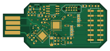
Uart384 is an open source FPGA PCB design by dpiegdon, published on GitHub. It is a 2-layer board measuring 54.1 × 23.5 mm, with 41 components from 23 distinct parts.
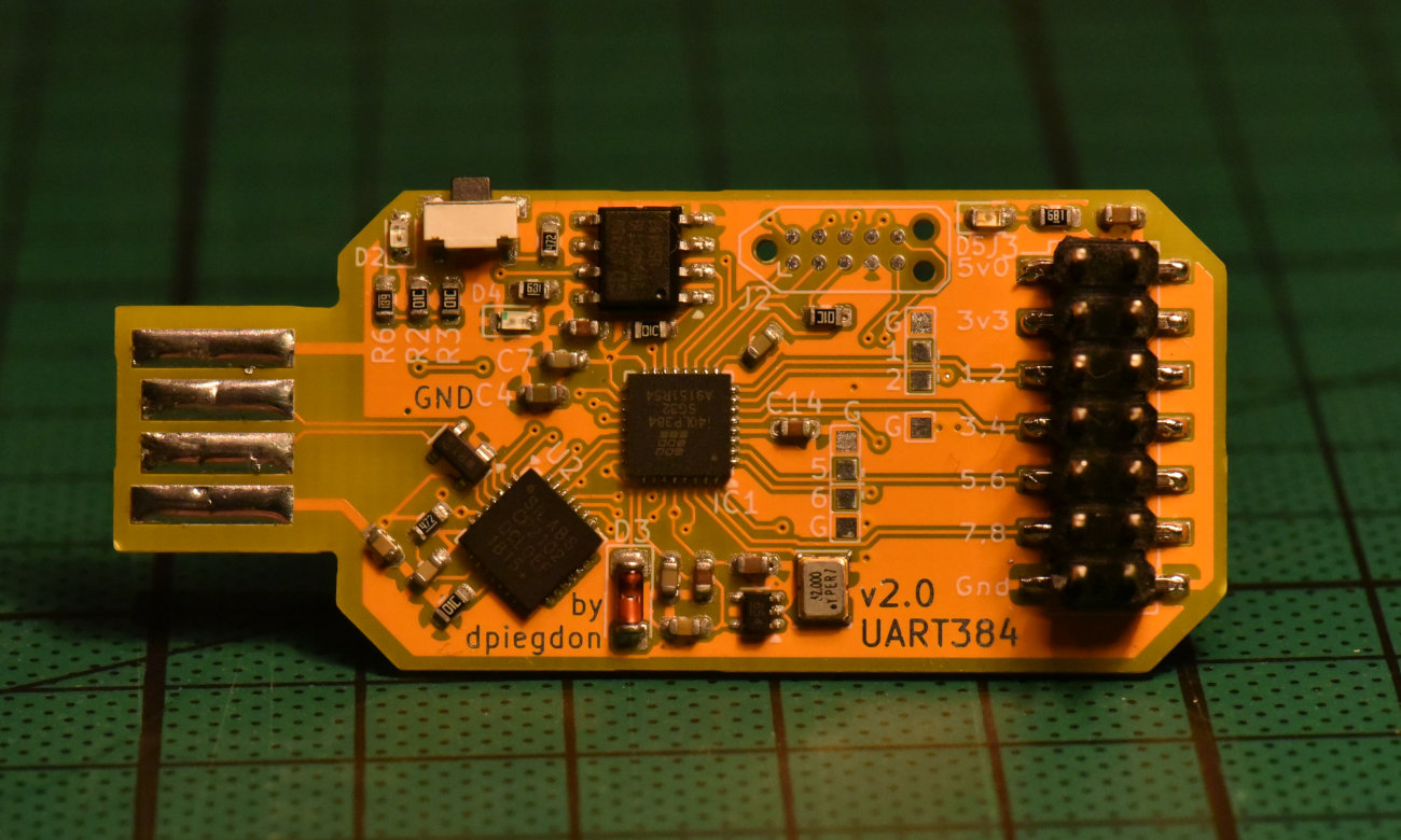
Its main chip is the ICE40LP384-SG32, from the FPGA family. Other key parts include the AT25DF256-SSHN, CP2102-QFN28, MIC5365-1.2YC5, AMS1117-2.5 and XC6206P182MR. By type, the board carries 14 capacitors, 10 resistors, 6 ICs, 5 diodes, 4 connectors and 1 crystal.
It belongs with the dev boards & breakouts and usb & debug tools designs in this gallery.
From the project
USB-based mini-devboard for the Lattice iCE40LP384 FPGA
UART384 - FPGA devboard & USB-stick ===================================
This is a mini-devboard for the Lattice iCE40LP384, the BEST 🔍 FPGA ever!
Features: - USB-stick form-factor - USB is connected to Silabs CP2102 USB-to-UART bridge - Tiny Lattice iCE40LP384 with connections: - 384 LUTs/FFs - UART - 2 LEDs - 1 push-button - 8 GPIOs on pinheader - 32MHz oscillator - small flash for bitstream - TC2050 connector (bottom side) for programming the flash
Main components on the Uart384
Uart384 bill of materials (BOM)
41 components, 23 distinct parts.
| Qty | Part | Footprint | Refs |
|---|---|---|---|
| 1 | ICE40LP384-SG32 | QFN-32-1EP_5x5mm_P0.5mm_EP3.6x3.6mm | IC1 |
| 1 | AT25DF256-SSHN | SOIC-8_3.9x4.9mm_P1.27mm | U1 |
| 1 | CP2102-QFN28 | QFN-28-1EP_5x5mm_P0.5mm_EP3.35x3.35mm | U2 |
| 1 | MIC5365-1.2YC5 | SOT-353_SC-70-5 | U3 |
| 1 | AMS1117-2.5 | SOT-223-3_TabPin2 | U4 |
| 1 | XC6206P182MR | SOT-23-3 | U5 |
| 1 | XO32 | Oscillator_SMD_EuroQuartz_XO32-4Pin_3.2x2.5mm | Y1 |
| 1 | USB_A | CONN-USB-A-PCB-TRACES | J1 |
| 1 | TC2050 | Tag-Connect_TC2050-IDC-NL_2x05_P1.27mm_Vertical | J2 |
| 1 | TC2050_ext | PinHeader_2x05_P2.54mm_Vertical_SMD | J3 |
| 1 | Conn_02x07_Odd_Even | PinHeader_2x07_P2.54mm_Vertical_SMD | J4 |
| 1 | SW_Push | TS-1224W_Side_Button_2x4x3.3mm_3.5mm_3.8mm_SMD_Aliexpress | SW1 |
| 1 | PRTR5V0U2X | SOT-143 | D1 |
| 1 | LED_ORANGE | LED_0603_1608Metric | D2 |
| 1 | LL4148 | D_MiniMELF | D3 |
| 1 | LED1_RED | LED_0603_1608Metric | D4 |
| 1 | LED2_GREEN | LED_0603_1608Metric | D5 |
| 7 | 100n | C_0603_1608Metric | C1, C3, C7, C9, C10, C13, C14 |
| 5 | 1u | C_0603_1608Metric | C2, C5, C6, C11, C12 |
| 2 | 4u7 | C_0603_1608Metric | C4, C8 |
Show 3 more
| Qty | Part | Footprint | Refs |
|---|---|---|---|
| 5 | 10K | R_0603_1608Metric | R1, R2, R3, R5, R10 |
| 2 | 4k7 | R_0603_1608Metric | R4, R8 |
| 3 | 680 | R_0603_1608Metric | R6, R7, R9 |
Uart384 design files
The KiCad project lives in the dpiegdon/uart384 repository on GitHub; these links point at the commit this page was built from.
- Layoutpcb/uart384.kicad_pcb
- Schematicpcb/uart384.kicad_sch
Uart384: common questions
What microcontroller does the Uart384 use?
The Uart384 is built around the ICE40LP384-SG32, from the FPGA family.
How big is the Uart384 PCB?
The Uart384 measures 54.1 × 23.5 mm, has 2 copper layers and is 1.6 mm thick.
How many components are on the Uart384?
41 components, from 23 distinct parts. The full bill of materials is listed on this page.
Where can I download the Uart384 design files?
From the dpiegdon/uart384 repository on GitHub, which has the KiCad layout and the schematic; the links under Design files point to each one.
Can I use the Uart384 design in my own project?
The repository has no license, so all rights stay with dpiegdon. Use it as a reference, and ask the author before reusing the design.
Can I test firmware for the Uart384 without the hardware?
Yes. HardLabs builds a simulation of the board from its netlist and BOM, so you can run and debug FPGA firmware against it before you order a PCB.
Similar boards
 FPGA
Base board
GlasgowEmbedded
80 × 49 mm222 parts4L0BSD2.2k FPGA
Thunderscope Rev5.3
EEVengers
122.5 × 103.5 mm817 parts6LMIT1.3k FPGA
Usb sniffer
ataradov
58.2 × 38.1 mm86 parts2LBSD-3-Clause1.3k FPGA
Tomu, I'm
theacodes
13 × 9.4 mm40 parts4LMIT1.1k FPGA
Icepi zero
cheyao
65 × 30 mm143 parts4LSHL-2.1865 FPGA
Gcvideo
ikorb
49 × 30 mm44 parts4LNo license765