
VFD-HMI-Module

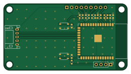
About the VFD-HMI-Module
VFD-HMI-Module is an open source ESP32 PCB design by DriveLink-HM, published on GitHub under the GPL-3.0 license. It is a 2-layer board measuring 65 × 35 mm, with 21 components from 12 distinct parts.
Its main chip is the ESP32-S3-WROOM-1, from the ESP32 family. By type, the board carries 8 capacitors, 7 resistors, 3 connectors, 2 switches and 1 IC.
It belongs with the displays & leds and iot & wireless designs in this gallery.
From the project
A Variable Frequency Drive, designed and built for Projekt Mechatronik in SoSe26
An open-hardware variable frequency drive (VFD) for three-phase induction motors, developed for the course Projekt Mechatronik at Munich University of Applied Sciences (HM).
DriveLink rectifies single-phase 230 V AC mains into a ≈325 V DC link and drives the motor through an Infineon IM06B50GC1 CIPOS Mini intelligent power module (600 V / 50 A). The power stage is controlled by an STM32G474 whose firmware is generated from a PLECS model, while a detachable ESP32-S3 HMI provides an OLED display, rotary-encoder control, and a WiFi web dashboard. This repository contains everything needed to…
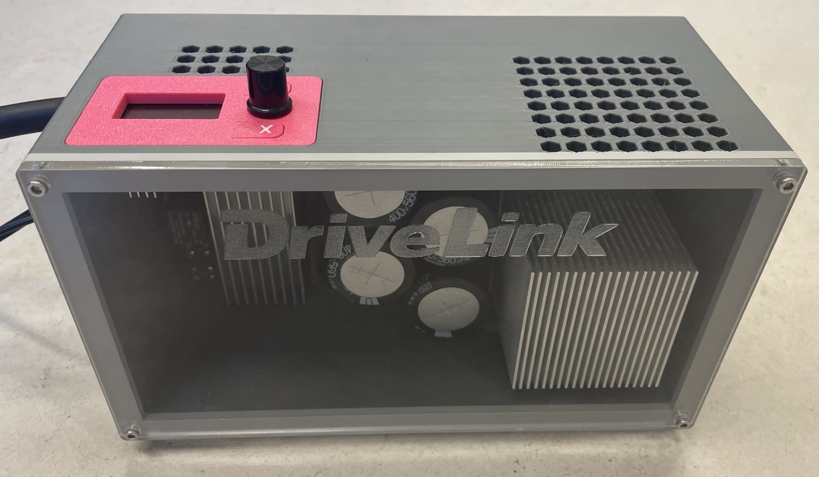
Main components on the VFD-HMI-Module
VFD-HMI-Module bill of materials (BOM)
21 components, 12 distinct parts.
| Qty | Part | Footprint | Refs |
|---|---|---|---|
| 1 | ESP32-S3-WROOM-1 | ESP32-S3-WROOM-1 | U1 |
| 1 | Conn_01x04_Pin | PinHeader_1x04_P2.54mm_Vertical | J1 |
| 1 | Conn_01x05_Socket | JST_PH_S5B-PH-K_1x05_P2.00mm_Horizontal | J2 |
| 1 | Conn_01x09_Pin | PinHeader_1x09_P2.54mm_Vertical | J3 |
| 2 | SW_Push | SW_Push_1P1T_NO_Vertical_Wuerth_434133025816 | SW0, SW1 |
| 1 | 10u | C_0603_1608Metric | C1 |
| 3 | 0.1u | C_0603_1608Metric | C2, C4, C8 |
| 1 | 1u | C_0603_1608Metric | C3 |
| 3 | DNP | C_0603_1608Metric | C5, C6, C7 |
| 3 | DNP | R_0603_1608Metric | R1, R2, R3 |
| 2 | 10k | R_0603_1608Metric | R5, R8 |
| 2 | 4.7k | R_0603_1608Metric | R6, R7 |
VFD-HMI-Module design files
The KiCad project lives in the DriveLink-HM/DriveLink repository on GitHub; these links point at the commit this page was built from.
VFD-HMI-Module: common questions
What microcontroller does the VFD-HMI-Module use?
The VFD-HMI-Module is built around the ESP32-S3-WROOM-1, from the ESP32 family.
How big is the VFD-HMI-Module?
The VFD-HMI-Module measures 65 × 35 mm, has 2 copper layers and is 1.6 mm thick.
How many components are on the VFD-HMI-Module?
21 components, from 12 distinct parts. The full bill of materials is listed on this page.
Where can I download the VFD-HMI-Module design files?
From the DriveLink-HM/DriveLink repository on GitHub, which has the KiCad layout and the schematic; the links under Design files point to each one.
Can I use the VFD-HMI-Module design in my own project?
Yes, under the terms of its GPL-3.0 license, which DriveLink-HM chose for the repository.
Can I test firmware for the VFD-HMI-Module without the hardware?
Yes. HardLabs builds a simulation of the board from its netlist and BOM, so you can run and debug ESP32 firmware against it before you order a PCB.
More boards in DriveLink
Similar boards
 ESP32
ESP32Open Book Abridged Edition
joeycastillo
85 × 115 mm65 parts2LCC-BY-SA-4.08.1k ESP32
ESP32Esp32 minimal
atopile
36.2 × 26.8 mm20 parts2LMIT4.0k ESP32
ESP32Badge
56.3 × 39 mm239 parts4LMIT4.0k ESP32
ESP32Controller
StuckAtPrototype
29 × 74 mm58 parts4LApache-2.03.8k ESP32
ESP32Racer
36 × 50.2 mm70 parts4LApache-2.03.8k ESP32
ESP32Bitaxe
skot
56.5 × 99.8 mm86 parts4LCERN-OHL-S-2.01.4k