
R3 power

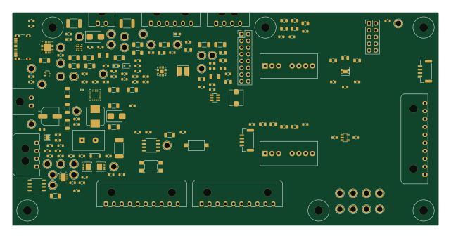
About the R3 power PCB
R3 power is an open source PCB design by druzvv-hash, published on GitHub. It is a 4-layer board measuring 160 × 80 mm, with 156 components from 136 distinct parts.
Other key parts include the TPS62132RGTR, TPS54302DDCR, RS3E-0505S/H3, ADM7150ACPZ-3.3-R7 and TPS7A2033PDBVR. By type, the board carries 71 capacitors, 35 resistors, 13 connectors, 11 ICs, 10 inductors and 7 diodes.
It belongs with the power & battery and displays & leds designs in this gallery.
From the project
ESP32-S3 + INA228 logger: hardware bring-up with SD, SH1106 OLED, 24C32 EEPROM and DS3231 RTC.
Editable KiCad 10 project for the R3 power module. The schematic uses one root page and ten functional child sheets so battery/BMS, charger/power-path, user system-power control, primary converters, isolation, LDOs, INA bipolar power and connectors can be reviewed independently.
Open R3power.kicadpro in KiCad 10. The canonical schematic is R3power.kicadsch; the PCB file is R3power.kicadpcb.
Main components on the R3 power
R3 power bill of materials (BOM)
156 components, 136 distinct parts — part numbers from the project's BOM.
| Qty | Part | Footprint | Refs |
|---|---|---|---|
| 1 | TPS62132RGTR | VQFN-16-1EP_3x3mm_P0.5mm_EP1.45x1.45mm | U1 |
| 1 | TPS54302DDCR | SOT-23-6 | U2 |
| 1 | RS3E-0505S/H3 | Converter_DCDC_RECOM_RS3E_SIP8 | U3 |
| 1 | ADM7150ACPZ-3.3-R7 | LFCSP-8-1EP_3x3mm_P0.5mm_EP1.74x1.45mm | U4 |
| 1 | TPS7A2033PDBVR | SOT-23-5 | U5 |
| 1 | RS3-0505D/H3 | Converter_DCDC_RECOM_RS3_SIP8 | U6 |
| 1 | TPS2121RUXR | Texas_VQFN-HR-12_2x2.5mm_P0.5mm | U7 |
| 1 | BQ25798RQM | Texas_RQM0029A_VQFN-29_4x4mm_P0.4mm | U8 |
| 1 | BQ28Z610DRZR | Texas_DRZ0012A_VSON-12 | U9 |
| 1 | STUSB4500QTR | QFN-24-1EP_4x4mm_P0.5mm_EP2.7x2.7mm | U10 |
| 1 | BQ294502 SPACE ONLY / NC / DNP | WSON-6-1EP_2x2mm_P0.65mm_EP1x1.6mm | U11 |
| 1 | DMP3007LSS-13 | DMP3007LSS_SO8_LOGICAL | Q1 |
| 1 | CSD17577Q3AT 30V NMOS DSG | CSD17577Q3A_VSON-8_3.3x3.3mm | Q2 |
| 1 | CSD17577Q3AT 30V NMOS CHG | CSD17577Q3A_VSON-8_3.3x3.3mm | Q3 |
| 1 | DMP3007LSS-13 SYSTEM LOAD SWITCH | DMP3007LSS_SO8_LOGICAL | Q4 |
| 1 | SERVICE / BENCH INPUT 6-12V | Molex_Micro-Fit_3.0_43650-0200_1x02_P3.00mm_Horizontal | J1 |
| 1 | DIGITAL POWER OUT | Molex_Micro-Fit_3.0_43650-0600_1x06_P3.00mm_Horizontal | J2 |
| 1 | ISOLATED POWER OUT | Molex_Micro-Fit_3.0_43650-1000_1x10_P3.00mm_Horizontal | J3 |
| 1 | CONTROL / SERVICE | Molex_Micro-Fit_3.0_43650-0400_1x04_P3.00mm_Horizontal | J4 |
| 1 | PRIMARY AUX DNP | JST_GH_SM04B-GHS-TB_1x04-1MP_P1.25mm_Horizontal | J5 |
Show 116 more
| Qty | Part | Footprint | Refs |
|---|---|---|---|
| 1 | ISOLATED AUX DNP | JST_GH_SM04B-GHS-TB_1x04-1MP_P1.25mm_Horizontal | J6 |
| 1 | USB-C POWER INPUT | USB_C_Receptacle_GCT_USB4105-xx-A_16P_TopMnt_Horizontal | J7 |
| 1 | 2S BATTERY / KEYED / NTC_BMS=103AT-2 | Molex_Micro-Fit_3.0_43650-0400_1x04_P3.00mm_Horizontal | J8 |
| 1 | NTC_CHG=103AT-2 / QUIET DGND RETURN | Molex_Micro-Fit_3.0_43650-0200_1x02_P3.00mm_Horizontal | J9 |
| 1 | BATTERY / CHARGER TELEMETRY | Molex_Micro-Fit_3.0_43650-1000_1x10_P3.00mm_Horizontal | J10 |
| 1 | USER PANEL / PRIMARY ONLY | Molex_Micro-Fit_3.0_43650-1000_1x10_P3.00mm_Horizontal | J11 |
| 1 | PRIMARY B2B 2x8 / DNP | PinHeader_2x08_P2.54mm_Vertical | J12 |
| 1 | ISOLATED B2B 2x5 / DNP | PinHeader_2x05_P2.54mm_Vertical | J13 |
| 1 | MF-R250-0-10 2.5A/30V PPTC | Fuse_PTC_MF-R250 | F1 |
| 1 | MF-MSMF260/16X-2 2.6A/16V PPTC | Fuse_1812_4532Metric_Pad1.30x3.40mm_HandSolder | F2 |
| 1 | MF-MSMF250/16X-2 2.5A/16V PPTC | Fuse_1812_4532Metric_Pad1.30x3.40mm_HandSolder | F3 |
| 1 | C&K RS282G05A3 / POWER ON | SW_SPST_CK_RS282G05A3 | SW1 |
| 1 | QON SERVICE / TL3305AF160QG | SW_SPST_TL3305A | SW2 |
| 1 | SMBJ13A / 13V VRWM | D_SMB | D1 |
| 1 | BZT52C10 | D_SOD-123 | D2 |
| 1 | SMBJ13A / 13V VRWM USB VBUS | D_SMB | D3 |
| 1 | ESDA25W CC ESD / P1,P2=CC P3=GND | SOT-323_SC-70 | D4 |
| 1 | LTST-C190KRKT RED / CHG | LED_0603_1608Metric | D5 |
| 1 | LTST-C190KGKT GREEN / RUN | LED_0603_1608Metric | D6 |
| 1 | BAT54WS-7-F STAT ISOLATION | D_SOD-323 | D7 |
| 1 | BLM31PG601SN1 | L_1206_3216Metric_Pad1.22x1.90mm_HandSolder | FB1 |
| 1 | FB_A / FB-or-0R | R_0805_2012Metric | FB2 |
| 1 | FB_D / FB-or-0R | R_0805_2012Metric | FB3 |
| 1 | FB_INA_P / FB-or-0R | R_0805_2012Metric | FB4 |
| 1 | FB_INA_N / FB-or-0R | R_0805_2012Metric | FB5 |
| 2 | BLM31KN601B family / 2A | L_1206_3216Metric_Pad1.22x1.90mm_HandSolder | FB6, FB7 |
| 1 | 2.2uH XFL4020-222ME | L_Coilcraft_XFL4020 | L1 |
| 1 | 10uH SRP5030TA-100M | L_Bourns_SRP5030T | L2 |
| 1 | 1.0uH >=6A / MPN TBD | L_Bourns_SRP7028A_7.3x6.6mm | L3 |
| 1 | 47uF/25V low-ESR | CP_Elec_6.3x5.8 | C1 |
| 4 | 100nF/25V | C_0603_1608Metric | C2, C4, C11, C21 |
| 1 | 22uF/25V | C_1206_3216Metric | C3 |
| 2 | 10uF/25V | C_1206_3216Metric | C10, C20 |
| 4 | 22uF/10V | C_0805_2012Metric | C12, C13, C23, C24 |
| 1 | 3.3nF | C_0603_1608Metric | C14 |
| 1 | 100nF BOOT | C_0603_1608Metric | C22 |
| 1 | 75pF C0G | C_0603_1608Metric | C25 |
| 1 | 10uF/10V ADS IN | C_0805_2012Metric | C26 |
| 1 | 100nF ADS IN | C_0603_1608Metric | C27 |
| 1 | 10uF/10V INA IN | C_0805_2012Metric | C28 |
| 1 | 100nF INA IN | C_0603_1608Metric | C29 |
| 1 | 10uF/10V RAW | C_0805_2012Metric | C30 |
| 1 | 100nF RAW | C_0603_1608Metric | C31 |
| 1 | 10uF A bulk | C_0805_2012Metric | C32 |
| 1 | 100nF A | C_0603_1608Metric | C33 |
| 1 | 10uF D bulk | C_0805_2012Metric | C34 |
| 1 | 100nF D | C_0603_1608Metric | C35 |
| 1 | 10uF VIN | C_0805_2012Metric | C40 |
| 1 | 10uF VREG | C_0805_2012Metric | C41 |
| 1 | 10uF VOUT | C_0805_2012Metric | C42 |
| 1 | 1uF REF | C_0603_1608Metric | C43 |
| 1 | 1uF BYP | C_0603_1608Metric | C44 |
| 1 | 2.2uF IN | C_0603_1608Metric | C50 |
| 1 | 4.7uF OUT | C_0603_1608Metric | C51 |
| 1 | 10uF +5V bulk | C_0805_2012Metric | C60 |
| 1 | 100nF +5V | C_0603_1608Metric | C61 |
| 1 | 10uF -5V bulk | C_0805_2012Metric | C62 |
| 1 | 100nF -5V | C_0603_1608Metric | C63 |
| 1 | 4.7nF SHIELD | C_0603_1608Metric | C70 |
| 1 | 10uF/25V USB | C_1206_3216Metric | C71 |
| 1 | 100nF MUX SS | C_0603_1608Metric | C72 |
| 1 | 10uF/25V MUX OUT | C_1206_3216Metric | C73 |
| 1 | 47nF BTST1 | C_0603_1608Metric | C74 |
| 1 | 47nF BTST2 | C_0603_1608Metric | C75 |
| 1 | 4.7uF REGN | C_0603_1608Metric | C76 |
| 3 | 10uF/25V PMID | C_1206_3216Metric | C77, C78, C79 |
| 1 | 100nF PMID | C_0603_1608Metric | C80 |
| 5 | 10uF/16V SYS | C_1206_3216Metric | C81, C82, C83, C84, C85 |
| 1 | 100nF SYS | C_0603_1608Metric | C86 |
| 2 | 10uF/16V BAT | C_1206_3216Metric | C87, C88 |
| 1 | 1nF SDRV | C_0603_1608Metric | C89 |
| 1 | 2.2uF PBI | C_0603_1608Metric | C93 |
| 1 | 100nF SHUNT DIFF | C_0603_1608Metric | C94 |
| 1 | 100nF DSG D-S / TI EVM | C_0603_1608Metric | C95 |
| 1 | 100nF CHG D-S / TI EVM | C_0603_1608Metric | C96 |
| 1 | 100nF VC2-VC1 / CELL2 | C_0603_1608Metric | C97 |
| 1 | 100nF VC1-VSS / CELL1 | C_0603_1608Metric | C98 |
| 1 | 100nF/25V VBUS LOCAL | C_0402_1005Metric | C100 |
| 3 | 10uF/25V VBUS LOCAL | C_1206_3216Metric | C101, C102, C103 |
| 1 | 1uF VREG_1V2 | C_0603_1608Metric | C104 |
| 1 | 1uF VREG_2V7 | C_0603_1608Metric | C105 |
| 1 | 4.7uF/25V PD VDD | C_0603_1608Metric | C106 |
| 1 | 100nF G-S / SOFT START | C_0603_1608Metric | C107 |
| 1 | 10uF/16V VSYS_MAIN | C_1206_3216Metric | C108 |
| 2 | 100k | R_0603_1608Metric | R1, R10 |
| 1 | 100k 1% | R_0603_1608Metric | R21 |
| 1 | 13.3k 1% | R_0603_1608Metric | R22 |
| 1 | 10k | R_0603_1608Metric | R40 |
| 1 | 1M SHIELD | R_0603_1608Metric | R72 |
| 1 | 44.2k / ILIM typ 2.5A | R_0603_1608Metric | R73 |
| 1 | 100R BATP | R_0603_1608Metric | R74 |
| 1 | 6.04k PROG / 2S PROFILE | R_0603_1608Metric | R75 |
| 1 | 243k ILIM TOP / DEFAULT 0.50A | R_0603_1608Metric | R76 |
| 1 | 100k ILIM BOT | R_0603_1608Metric | R77 |
| 1 | 5.24k TS TOP | R_0603_1608Metric | R78 |
| 1 | 30.31k TS BOT | R_0603_1608Metric | R79 |
| 1 | 10k CHARGE_STATUS PU | R_0603_1608Metric | R80 |
| 1 | 10k INT PU | R_0603_1608Metric | R81 |
| 1 | 10k MUX ST PU | R_0603_1608Metric | R82 |
| 1 | 10k ALERT PU | R_0603_1608Metric | R83 |
| 1 | 10k PDO3 OK PU | R_0603_1608Metric | R84 |
| 1 | 0R PD VDD FEED | R_0603_1608Metric | R85 |
| 1 | 100R VC2 / KELVIN | R_0603_1608Metric | R90 |
| 1 | 100R VC1 / KELVIN | R_0603_1608Metric | R91 |
| 1 | 100R TS | R_0603_1608Metric | R92 |
| 1 | WSL2512R0100FEA 10mR 1W | R_2512_6332Metric_Pad1.40x3.35mm_HandSolder | R93 |
| 2 | 100R KELVIN | R_0603_1608Metric | R94, R95 |
| 2 | 10k I2C | R_0603_1608Metric | R96, R97 |
| 1 | 5.1k DSG GATE / TI EVM | R_0603_1608Metric | R98 |
| 1 | 10M DSG G-S / TI EVM | R_0603_1608Metric | R99 |
| 1 | 5.1k CHG GATE / TI EVM | R_0603_1608Metric | R100 |
| 1 | 10M CHG G-S / TI EVM | R_0603_1608Metric | R101 |
| 1 | 100k G-S / DEFAULT OFF | R_0603_1608Metric | R102 |
| 1 | 10k GATE SERIES | R_0603_1608Metric | R103 |
| 1 | 2.2k CHG LED / ~1.3mA | R_0603_1608Metric | R104 |
| 1 | 2.2k RUN LED / ~0.7mA | R_0603_1608Metric | R105 |
R3 power design files
The KiCad project lives in the druzvv-hash/r1-s3-logger repository on GitHub; these links point at the commit this page was built from.
R3 power: common questions
How big is the R3 power PCB?
The R3 power measures 160 × 80 mm, has 4 copper layers and is 1.6 mm thick.
How many components are on the R3 power?
156 components, from 136 distinct parts, with part numbers taken from the project's own BOM. The full bill of materials is listed on this page.
Where can I download the R3 power design files?
From the druzvv-hash/r1-s3-logger repository on GitHub, which has the KiCad layout, the schematic and the BOM; the links under Design files point to each one.
Can I use the R3 power design in my own project?
The repository has no license, so all rights stay with druzvv-hash. Use it as a reference, and ask the author before reusing the design.
Similar boards
BM28B0.6-24DSBreakout
scottbez1
15.2 × 35.6 mm3 parts2LApache-2.022.2k
LevelShifterBreakout
15.2 × 20.3 mm5 parts2LApache-2.022.2k
View base
81.2 × 81.2 mm81 parts2LApache-2.022.2k
View screen
35 × 35 mm12 parts2LApache-2.022.2k
Display eval
byrantech
52.1 × 22.6 mm12 parts4LMIT4.3k
ChainlinkBase
98.4 × 190.5 mm119 parts2LApache-2.04.2k