
StepperMotorController

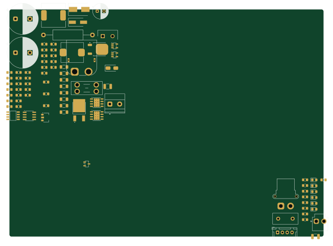
About the StepperMotorController PCB
StepperMotorController is an open source PCB design by efebasol, published on GitHub. It is a 2-layer board measuring 162.8 × 117.8 mm, with 85 components from 70 distinct parts.
Other key parts include the LM393DR2GH, TPS54360DDA, AP2112K-3.3, TL431D and MCP1416. By type, the board carries 29 resistors, 28 capacitors, 11 diodes, 8 ICs, 5 connectors and 2 inductors.
It belongs with the robotics & motion designs in this gallery.
From the project
Rev A — single-motor bench prototype power board. Feeds the driver board (48 V), the stepper motor brake (24 V) and the logic (5 V / 3V3).
Rev A — single-motor bench prototype power board. Feeds the driver board (48 V), the stepper motor brake (24 V) and the logic (5 V / 3V3).
Design calculations: docs/power-design-notes.md
Board-to-board by cables (no stacking / backplane).
Main-board side: 1 kΩ series resistor at the MCU ADC pin for VBUS_SENSE; one pull-up for FLT# (open-drain, active-low).
48 V, 24 V and SW nodes are routed on the 2 oz outer layers only (inner 1 oz layers can't carry or dissipate that current). Vias between L1 and L4 are fine — current flows in the plated barrel.
Main components on the StepperMotorController
StepperMotorController bill of materials (BOM)
85 components, 70 distinct parts.
| Qty | Part | Footprint | Refs |
|---|---|---|---|
| 1 | LM393DR2GH | SOIC127P600X175-8N | IC1 |
| 2 | TPS54360DDA | TI_SO-PowerPAD-8_ThermalVias | U1, U3 |
| 1 | AP2112K-3.3 | SOT-23-5 | U2 |
| 1 | TL431D Texas Instruments | SOIC-8_3.9x4.9mm_P1.27mm | U4 |
| 1 | MCP1416 | SOT-23-5 | U5 |
| 1 | TL431B_C54830630 hongjiacheng | SOT-23-3 | U6 |
| 1 | L78L12_SOT89 | SOT-89-3 | U7 |
| 1 | AOD4126 P40B10SL | AOD4185 | Q1 |
| 1 | Screw_Terminal_01x02 | TerminalBlock_Phoenix_MKDS-1,5-2-5.08_1x02_P5.08mm_Horizontal | J1 |
| 1 | 48V Input | AMASS_XT60PW-M_1x02_P7.20mm_Horizontal | J2 |
| 1 | 48V Output | AMASS_XT30PW-F_1x02_P2.50mm_Horizontal | J3 |
| 1 | 24V Brake Output | JST_VH_B2P-VH_1x02_P3.96mm_Vertical | J4 |
| 1 | Logic Output | JST_XH_B4B-XH-A_1x04_P2.50mm_Vertical | J5 |
| 1 | 100V 10A | Fuseholder_Blade_Mini_Keystone_3568 | F1 |
| 1 | 100V 3A <= 850mV | D_SMB-SMC_Universal_Handsoldering | D1 |
| 1 | 100V 5A | TO-252-2 | D2 |
| 1 | MBR10100 | TO508P482X997X1956-2P | D3 |
| 1 | SMBJ51A | D_SMA-SMB_Universal_Handsoldering | D4 |
| 1 | SS510 hongjiacheng | D_SMA | D5 |
| 1 | +48V | LED_0805_2012Metric_Pad1.15x1.40mm_HandSolder | D6 |
Show 50 more
| Qty | Part | Footprint | Refs |
|---|---|---|---|
| 1 | +VM | LED_0805_2012Metric_Pad1.15x1.40mm_HandSolder | D7 |
| 1 | +24V | LED_0805_2012Metric_Pad1.15x1.40mm_HandSolder | D8 |
| 1 | +12V | LED_0805_2012Metric_Pad1.15x1.40mm_HandSolder | D9 |
| 1 | +5V | LED_0805_2012Metric_Pad1.15x1.40mm_HandSolder | D10 |
| 1 | +3V3 | LED_0805_2012Metric_Pad1.15x1.40mm_HandSolder | D11 |
| 1 | 68uH | L_SXN_SMDRI125 | L1 |
| 1 | 22uH | L_Chilisin_BMRF00101040 | L2 |
| 2 | 100nF, 25V | C_0805_2012Metric_Pad1.18x1.45mm_HandSolder | C1, C12 |
| 6 | 2.2uF, 100V | C_1206_3216Metric_Pad1.33x1.80mm_HandSolder | C2, C3, C4, C13, C14, C15 |
| 2 | 1uF | C_0805_2012Metric_Pad1.18x1.45mm_HandSolder | C5, C6 |
| 1 | 68uF, 50V | CP_Radial_D8.0mm_P3.50mm | C7 |
| 2 | 10uF, 50V | C_1206_3216Metric_Pad1.33x1.80mm_HandSolder | C8, C9 |
| 1 | 24pF, 25V | C_0805_2012Metric_Pad1.18x1.45mm_HandSolder | C10 |
| 1 | 5.1nF, 25V | C_0805_2012Metric_Pad1.18x1.45mm_HandSolder | C11 |
| 2 | 22µF 25V X7R 1210 | C_1210_3225Metric_Pad1.33x2.70mm_HandSolder | C16, C27 |
| 1 | 220pF, 25V | C_0805_2012Metric_Pad1.18x1.45mm_HandSolder | C17 |
| 1 | 27nF, 25V | C_0805_2012Metric_Pad1.18x1.45mm_HandSolder | C18 |
| 1 | 100nF 100V | C_0805_2012Metric_Pad1.18x1.45mm_HandSolder | C19 |
| 2 | 470uF 100V | CP_Radial_D16.0mm_P7.50mm | C20, C21 |
| 1 | 0.33uF | C_0805_2012Metric_Pad1.18x1.45mm_HandSolder | C22 |
| 1 | 0.1uF | C_0805_2012Metric_Pad1.18x1.45mm_HandSolder | C23 |
| 1 | 4.7uF | C_0805_2012Metric_Pad1.18x1.45mm_HandSolder | C24 |
| 1 | 100nF 25V | C_0805_2012Metric_Pad1.18x1.45mm_HandSolder | C25 |
| 1 | 1uF 25V | C_0805_2012Metric_Pad1.18x1.45mm_HandSolder | C26 |
| 1 | 100nF YAGEO | C_0805_2012Metric_Pad1.18x1.45mm_HandSolder | C28 |
| 2 | 523kR | R_0805_2012Metric_Pad1.20x1.40mm_HandSolder | R1, R7 |
| 1 | 348kR | R_0805_2012Metric_Pad1.20x1.40mm_HandSolder | R2 |
| 2 | 267kR | R_0805_2012Metric_Pad1.20x1.40mm_HandSolder | R3, R9 |
| 1 | 36.5kR | R_0805_2012Metric_Pad1.20x1.40mm_HandSolder | R4 |
| 2 | 18.7kR | R_0805_2012Metric_Pad1.20x1.40mm_HandSolder | R5, R11 |
| 1 | 12kR | R_0805_2012Metric_Pad1.20x1.40mm_HandSolder | R6 |
| 1 | 60.4kR | R_0805_2012Metric_Pad1.20x1.40mm_HandSolder | R8 |
| 1 | 4.22kR | R_0805_2012Metric_Pad1.20x1.40mm_HandSolder | R10 |
| 1 | 11.5kR | R_0805_2012Metric_Pad1.20x1.40mm_HandSolder | R12 |
| 1 | 97.6kR | R_0805_2012Metric_Pad1.20x1.40mm_HandSolder | R13 |
| 1 | 243kR | R_0805_2012Metric_Pad1.20x1.40mm_HandSolder | R14 |
| 1 | 10kR | R_0805_2012Metric_Pad1.20x1.40mm_HandSolder | R15 |
| 1 | RX24, 50W, 33Ω | R_Axial_DIN0516_L15.5mm_D5.0mm_P25.40mm_Horizontal | R16 |
| 1 | 4.75kR | R_0805_2012Metric_Pad1.20x1.40mm_HandSolder | R17 |
| 1 | 10R | R_0805_2012Metric_Pad1.20x1.40mm_HandSolder | R18 |
| 1 | 1kR | R_0805_2012Metric_Pad1.20x1.40mm_HandSolder | R19 |
| 1 | 10k | R_0805_2012Metric_Pad1.20x1.40mm_HandSolder | R20 |
| 1 | NTC_5_20 Nanjing Shiheng Elec | NTC_Disc_D13mm_W5.5mm_P7.5mm | R21 |
| 1 | 100kΩ UNI-ROYAL(Uniroyal Elec) | R_0805_2012Metric_Pad1.20x1.40mm_HandSolder | R22 |
| 1 | 3.9kΩ UNI-ROYAL(Uniroyal Elec) | R_0805_2012Metric_Pad1.20x1.40mm_HandSolder | R23 |
| 2 | 33kΩ UNI-ROYAL(Uniroyal Elec) | R_0805_2012Metric_Pad1.20x1.40mm_HandSolder | R24, R25 |
| 1 | 15kΩ UNI-ROYAL(Uniroyal Elec) | R_0805_2012Metric_Pad1.20x1.40mm_HandSolder | R26 |
| 1 | 6.8kΩ UNI-ROYAL(Uniroyal Elec) | R_0805_2012Metric_Pad1.20x1.40mm_HandSolder | R27 |
| 1 | 2kΩ UNI-ROYAL(Uniroyal Elec) | R_0805_2012Metric_Pad1.20x1.40mm_HandSolder | R28 |
| 1 | 820Ω UNI-ROYAL(Uniroyal Elec) | R_0805_2012Metric_Pad1.20x1.40mm_HandSolder | R29 |
StepperMotorController design files
The KiCad project lives in the efebasol/StepperMotorController repository on GitHub; these links point at the commit this page was built from.
StepperMotorController: common questions
How big is the StepperMotorController PCB?
The StepperMotorController measures 162.8 × 117.8 mm, has 2 copper layers and is 1.6 mm thick.
How many components are on the StepperMotorController?
85 components, from 70 distinct parts. The full bill of materials is listed on this page.
Where can I download the StepperMotorController design files?
From the efebasol/StepperMotorController repository on GitHub, which has the KiCad layout and the schematic; the links under Design files point to each one.
Can I use the StepperMotorController design in my own project?
The repository has no license, so all rights stay with efebasol. Use it as a reference, and ask the author before reusing the design.
Similar boards

Stack chan
stack-chan
50 × 50 mm33 parts2LApache-2.01.7k
Cube batteryboard
willem-pennings
95 × 95 mm4 parts2LGPL-3.01.1k
Mesabob
rene-dev
87.5 × 50 mm44 parts2LGPL-3.0979
Bob
100 × 100 mm140 parts2LGPL-3.0979
Triple adapter
57 × 75 mm26 parts2LGPL-3.0979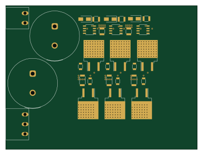
Trollerv2
100 × 75 mm33 parts4LGPL-3.0979