
Faultycat

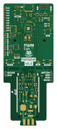
About the Faultycat PCB
Faultycat is an open source RP2040/RP2350 PCB design by ElectronicCats, published on GitHub under the BSD-3-Clause license. It is a 2-layer board measuring 51.2 × 124.2 mm, with 94 components from 59 distinct parts.
Its main chip is the IRLML2502, from the RP2040/RP2350 family. Other key parts include the AP2112K-3.3, W25Q16JV, RP2040, TXS0108EPW and TLV75718PDBV. By type, the board carries 25 resistors, 24 capacitors, 11 connectors, 10 diodes, 7 transistors and 7 switches.
From the project
Faulty Cat is a low-cost Electromagnetic Fault Injection (EMFI) tool, designed specifically for self-study and hobbiest research.
Faulty Cat is a low-cost Electromagnetic Fault Injection (EMFI) tool, designed specifically for self-study and hobbiest research.
Faulty Cat is a high-end Electromagnetic Fault Injection (EMFI) tool a remix of the project ChipSHOUTER PicoEMP design optimization focused in rough order on (1) safe operation, (2) high performance, (3) usability, and finally (4) cost. This results in a tool that covers many use-cases, but may be overkill (and expensive) for many.
Main components on the Faultycat
Faultycat bill of materials (BOM)
94 components, 59 distinct parts — part numbers from the project's BOM.
| Qty | Part | Footprint | Refs |
|---|---|---|---|
| 1 | AP2112K-3.3 | SOT-23-5 | U1 |
| 1 | W25Q16JV | W25Q16JVUUIQ | U2 |
| 1 | RP2040 | RP2040-QFN-56 | U3 |
| 1 | TXS0108EPW | TSSOP-20_4.4x6.5mm_P0.65mm | U4 |
| 1 | TLV75718PDBV | SOT-23-5 | U5 |
| 1 | SN74LVC1T45DBV | SOT-23-6 | U6 |
| 2 | AO3422 | SOT-23 | Q1, Q2 |
| 1 | LDA111STR | SOP254P952X470-6N | Q3 |
| 1 | RGT16BM65DTL | TO-252-3_TabPin2 | Q4 |
| 1 | DMG3415U-7 | SOT-23 | Q5 |
| 1 | IRLML2502 | SOT-23 | Q7 |
| 1 | IRF7807PBF | SOIC-8_SI | Q8 |
| 1 | 12MHZ 12Mhz | Crystal_SMD_5032-2Pin_5.0x3.2mm | Y1 |
| 1 | Antenna | 732511150 | J1 |
| 1 | BG306-02-A-2-0400-L-G | BG30602A20400LG | J2 |
| 1 | CONN_01X10 Conn_01x10 | PinSocket_1x10_P2.54mm_Vertical | J3 |
| 1 | Header 2 | PinHeader_1x02_P2.54mm_Vertical | J4 |
| 1 | Header 4 | PinHeader_1x04_P2.54mm_Vertical | J5 |
| 1 | Input Power:2x AA Battery | PinHeader_1x02_P2.54mm_Vertical | J6 |
| 1 | GLITCHER_EN | PinSocket_1x02_P2.54mm_Vertical | J7 |
Show 39 more
| Qty | Part | Footprint | Refs |
|---|---|---|---|
| 1 | ANALOG_PINS | PinSocket_1x02_P2.54mm_Vertical | J8 |
| 1 | TRIGGER_IN | PinSocket_1x02_P2.54mm_Vertical | J9 |
| 1 | TRIGGER_VREF | PinSocket_1x02_P2.54mm_Vertical | J10 |
| 1 | USB_C_PLUG_USB2.0 USB_C_Plug_USB2.0 | C393939 | P1 |
| 1 | 0.5A | Fuse_0805_2012Metric | F1 |
| 3 | TL3305AF260QG | TL3305AF160QG | SW1, SW3, SW6 |
| 1 | ON | OS102011MA1QN1 | SW2 |
| 1 | RESET | SW_SPST_TL3342 | SW4 |
| 1 | BOOT | SW_SPST_TL3342 | SW5 |
| 1 | SW_SP3T | Sw3P1T | SW7 |
| 2 | ATB322524 | ATB3225240110T000 | T1, T2 |
| 4 | SM4005PL-TP | D_SOD-123F | D1, D2, D3, D10 |
| 1 | MURA160T3G | D_SMA | D4 |
| 1 | MM3ZXX MM3Zxx | D_SOD-323F | D5 |
| 1 | MBR120 | D_SOD-123 | D6 |
| 1 | H.V.Detected | LED_0603_1608Metric | D7 |
| 1 | Status | LED_0603_1608Metric | D8 |
| 1 | Charge On | LED_0603_1608Metric | D9 |
| 2 | 4.7UF 4.7uF | C_0805_2012Metric | C1, C3 |
| 3 | 100NF 100nF | C_0603_1608Metric | C2, C21, C22 |
| 1 | 0.47UF 0.47uF | CAPC6153X500N | C4 |
| 2 | 10UF 10uF | C_0402_1005Metric | C5, C6 |
| 10 | 100NF 100nF | C_0402_1005Metric | C7, C11, C12, C14, C15, C16, C17, C18 +2 |
| 2 | 27PF 27pF | C_0603_1608Metric | C8, C10 |
| 2 | 1UF 1uF | C_0603_1608Metric | C9, C13 |
| 2 | 10uF | C_0402_1005Metric | C23, C24 |
| 2 | 10R | R_0603_1608Metric | R1, R9 |
| 2 | 5.1K | R_0603_1608Metric | R2, R4 |
| 1 | 75R | R_0805_2012Metric | R3 |
| 6 | 1K | R_0603_1608Metric | R5, R6, R13, R14, R16, R18 |
| 1 | 22K | R_0603_1608Metric | R7 |
| 1 | 2K | R_0805_2012Metric | R8 |
| 1 | 20M | R_2010_5025Metric | R10 |
| 1 | 300K | RESC6432X120N | R11 |
| 1 | 100K | R_0603_1608Metric | R12 |
| 1 | 4.7K 4.7k | R_0603_1608Metric | R15 |
| 4 | 10K 10k | R_0603_1608Metric | R17, R21, R25, R26 |
| 2 | 27 | R_0603_1608Metric | R19, R20 |
| 2 | 1R | R_0603_1608Metric | R23, R24 |
Faultycat design files
The KiCad project lives in the ElectronicCats/faultycat repository on GitHub; these links point at the commit this page was built from.
- LayoutHardware/FaultyCat.kicad_pcb
- SchematicHardware/FaultyCat.kicad_sch
- BOMHardware/BOM.csv
Faultycat: common questions
What microcontroller does the Faultycat use?
The Faultycat is built around the IRLML2502, from the RP2040/RP2350 family.
How big is the Faultycat PCB?
The Faultycat measures 51.2 × 124.2 mm, has 2 copper layers and is 1.6 mm thick.
How many components are on the Faultycat?
94 components, from 59 distinct parts, with part numbers taken from the project's own BOM. The full bill of materials is listed on this page.
Where can I download the Faultycat design files?
From the ElectronicCats/faultycat repository on GitHub, which has the KiCad layout, the schematic and the BOM; the links under Design files point to each one.
Can I use the Faultycat design in my own project?
Yes, under the terms of its BSD-3-Clause license, which ElectronicCats chose for the repository.
Can I test firmware for the Faultycat without the hardware?
Yes. HardLabs builds a simulation of the board from its netlist and BOM, so you can run and debug RP2040/RP2350 firmware against it before you order a PCB.
Similar boards
 RP2040/RP2350
Open Book Abridged Edition
joeycastillo
85 × 115 mm29 parts2LCC-BY-SA-4.08.1k RP2040/RP2350
Corne
foostan
277.2 × 107.5 mm164 parts2LCC-BY-4.07.7k RP2040/RP2350
Corne
277.2 × 107.5 mm164 parts2LCC-BY-4.07.7k RP2040/RP2350
Msa
Mentra-Community
47.8 × 9.4 mm53 parts2LMIT1.2k RP2040/RP2350
Open Source Smart Glasses
93 × 10.5 mm80 parts4LMIT1.2k RP2040/RP2350
MSA
30.5 × 138 mm61 parts2LMIT1.2k