
RP2040-Breakout-Board

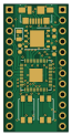
About the RP2040-Breakout-Board
RP2040-Breakout-Board is an open source RP2040/RP2350 PCB design by EPSILON0-dev, published on GitHub under the MIT license. It is a 4-layer board measuring 15.2 × 30.5 mm, with 32 components from 17 distinct parts.
Its main chip is the RP2040, from the RP2040/RP2350 family. Other key parts include the AP1117-33 and W25Q128JVS. By type, the board carries 16 capacitors, 6 resistors, 3 ICs, 3 connectors, 2 switches and 1 crystal.
It belongs with the dev boards & breakouts designs in this gallery.
From the project
Minimal RP2040 breakout board with USB Micro-B, 16 MB QSPI flash, boot and reset buttons, and breadboard-friendly GPIO headers.
Minimal RP2040 breakout with USB Micro-B, 16 MB QSPI flash, and full GPIO headers in a breadboard-friendly form factor.
Gerber files are in the gerber/ directory, ready to upload to JLCPCB, PCBWay, or equivalent.
- [x] Designed, not yet ordered - [x] Ordered — awaiting boards - [x] Assembled, untested - [x] Tested and working
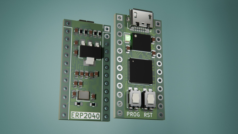
Main components on the RP2040-Breakout-Board
RP2040-Breakout-Board bill of materials (BOM)
32 components, 17 distinct parts.
| Qty | Part | Footprint | Refs |
|---|---|---|---|
| 1 | AP1117-33 | SOT-223-3_TabPin2 | U1 |
| 1 | W25Q128JVS | WSON-8-1EP_6x5mm_P1.27mm_EP3.4x4mm | U2 |
| 1 | RP2040 | QFN-56-1EP_7x7mm_P0.4mm_EP3.2x3.2mm | U3 |
| 1 | 12MHz | Crystal_SMD_3225-4Pin_3.2x2.5mm | Y1 |
| 1 | USB_B_Micro | USB_Micro-B_Molex_47346-0001 | J1 |
| 2 | Conn_01x12 | PinHeader_1x12_P2.54mm_Vertical | J2, J3 |
| 1 | USB_BOOT | SW_SPST_EVQP2 | SW1 |
| 1 | RESET | SW_SPST_EVQP2 | SW2 |
| 1 | LED | LED_0805_2012Metric | D1 |
| 4 | 1u | C_0603_1608Metric | C1, C2, C3, C6 |
| 10 | 100n | C_0603_1608Metric | C4, C5, C7, C8, C9, C10, C12, C14 +2 |
| 2 | 15p | C_0603_1608Metric | C11, C13 |
| 1 | 1k | R_0603_1608Metric | R1 |
| 1 | 47k | R_0603_1608Metric | R2 |
| 1 | 10k | R_0603_1608Metric | R3 |
| 2 | 28 | R_0603_1608Metric | R4, R5 |
| 1 | 2k2 | R_0603_1608Metric | R6 |
RP2040-Breakout-Board design files
The KiCad project lives in the EPSILON0-dev/RP2040-Breakout-Board repository on GitHub; these links point at the commit this page was built from.
- LayoutRP2040.kicad_pcb
- SchematicRP2040.kicad_sch
RP2040-Breakout-Board: common questions
What microcontroller does the RP2040-Breakout-Board use?
The RP2040-Breakout-Board is built around the RP2040, from the RP2040/RP2350 family.
How big is the RP2040-Breakout-Board?
The RP2040-Breakout-Board measures 15.2 × 30.5 mm, has 4 copper layers and is 1.6 mm thick.
How many components are on the RP2040-Breakout-Board?
32 components, from 17 distinct parts. The full bill of materials is listed on this page.
Where can I download the RP2040-Breakout-Board design files?
From the EPSILON0-dev/RP2040-Breakout-Board repository on GitHub, which has the KiCad layout and the schematic; the links under Design files point to each one.
Can I use the RP2040-Breakout-Board design in my own project?
Yes, under the terms of its MIT license, which EPSILON0-dev chose for the repository.
Can I test firmware for the RP2040-Breakout-Board without the hardware?
Yes. HardLabs builds a simulation of the board from its netlist and BOM, so you can run and debug RP2040/RP2350 firmware against it before you order a PCB.
Similar boards
 RP2040/RP2350
Open Book Abridged Edition
joeycastillo
85 × 115 mm29 parts2LCC-BY-SA-4.08.1k RP2040/RP2350
Corne
foostan
277.2 × 107.5 mm164 parts2LCC-BY-4.07.7k RP2040/RP2350
Corne
277.2 × 107.5 mm164 parts2LCC-BY-4.07.7k RP2040/RP2350
LogicAnalyzer
gusmanb
57 × 55.2 mm6 parts2LGPL-3.05.0k RP2040/RP2350
Jitx design
55.5 × 65 mm26 parts4LGPL-3.05.0k RP2040/RP2350
Pro V2
kata0510
290.1 × 130 mm270 parts2LMIT2.3k