
PNP MOBO V2

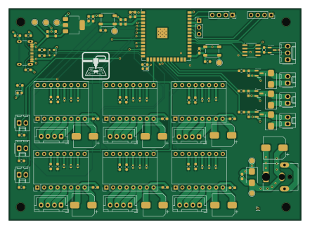
About the PNP MOBO V2 PCB
PNP MOBO V2 is an open source ESP32 PCB design by GabrielD98, published on GitHub under the MIT license. It is a 4-layer board measuring 110 × 80 mm, with 114 components from 32 distinct parts.
Its main chip is the ESP32-S3-WROOM-1, from the ESP32 family. Other key parts include the SN65HVD230, AMS1117-3.3 and Pololu_Breakout_DRV8825. By type, the board carries 49 resistors, 23 capacitors, 18 connectors, 8 diodes, 6 modules and 3 ICs.
It belongs with the robotics & motion and sensors designs in this gallery, and the repository also holds 1 earlier revision of it.
From the project
pick and place de PCB pour projet S4 de robotique
PCB design and schematics for the PickUS and PlacUS machine. Includes main control board and test board for validation.
The electrical work is split into two KiCad projects:
- PNPMOBOV1/ — Main control board for the machine - PNPTESTCIRCUITV1/` — Test board for validating pick and place operation
- KiCad 8 (recommended) - Basic soldering tools and bench power supply for bring-up - Optional for production: - PCB manufacturer account (JLCPCB, PCBWay, etc.) - Assembly service for SMT components
Main components on the PNP MOBO V2
PNP MOBO V2 bill of materials (BOM)
114 components, 32 distinct parts — part numbers from the project's BOM.
| Qty | Part | Footprint | Refs |
|---|---|---|---|
| 1 | ESP32-S3-WROOM-1 | ESP32-S3-WROOM-1 | U1 |
| 1 | SN65HVD230 | SOIC-8_3.9x4.9mm_P1.27mm | U3 |
| 1 | AMS1117-3.3 | SOT-223-3_TabPin2 | U4 |
| 6 | Pololu_Breakout_DRV8825 | Pololu_Breakout-16_15.2x20.3mm | A5, A6, A7, A8, A9, A10 |
| 3 | IRLML6244 | SOT-23 | Q1, Q2, Q4 |
| 1 | USB_C_Receptacle_USB2.0_16P | USB_C_Receptacle_GCT_USB4105-xx-A_16P_TopMnt_Horizontal | J1 |
| 6 | Conn_01x02_Pin | Molex_KK-254_AE-6410-02A_1x02_P2.54mm_Vertical | J3, J5, J7, J17, J18, J19 |
| 1 | Conn_01x03_Pin | PinHeader_1x03_P2.54mm_Vertical | J4 |
| 1 | Conn_01x03_Pin | Molex_KK-254_AE-6410-03A_1x03_P2.54mm_Vertical | J6 |
| 1 | Barrel_Jack_MountingPin | BarrelJack_CUI_PJ-063AH_Horizontal | J8 |
| 6 | Conn_01x04_Pin | JST_XH_B4B-XH-A_1x04_P2.50mm_Vertical | J9, J10, J11, J12, J13, J14 |
| 2 | Conn_01x04_Pin | PinSocket_1x04_P2.54mm_Vertical | J15, J16 |
| 2 | Conn_01x01_Pin | PinHeader_1x01_P1.00mm_Vertical | REF1, REF2 |
| 2 | SW_Push | SW_SPST_PTS647_Sx38 | SW1, SW2 |
| 1 | D_TVS | D_SMB | D1 |
| 3 | D | D_SMB | D2, D8, D9 |
| 1 | SP0503BAHT | SOT-143 | D3 |
| 2 | LED | LED_0603_1608Metric | D5, D6 |
| 1 | NUP2105L | SOT-23 | D7 |
| 12 | 0.1uF | C_0603_1608Metric_Pad1.08x0.95mm_HandSolder | C1, C8, C9, C13, C17, C21, C22, C24 +4 |
Show 12 more
| Qty | Part | Footprint | Refs |
|---|---|---|---|
| 3 | 10uf | C_0603_1608Metric_Pad1.08x0.95mm_HandSolder | C2, C12, C16 |
| 1 | 1uf/16V 10% | C_0603_1608Metric_Pad1.08x0.95mm_HandSolder | C7 |
| 7 | 100uF | CP_Elec_8x10 | C20, C23, C25, C27, C29, C31, C33 |
| 14 | 10k 1% | R_0603_1608Metric_Pad0.98x0.95mm_HandSolder | R1, R10, R40, R41, R42, R43, R44, R45 +6 |
| 2 | 22 | R_0603_1608Metric_Pad0.98x0.95mm_HandSolder | R2, R3 |
| 6 | 10k | R_0603_1608Metric_Pad0.98x0.95mm_HandSolder | R4, R8, R9, R11, R13, R16 |
| 2 | 5.1k | R_0603_1608Metric_Pad0.98x0.95mm_HandSolder | R5, R6 |
| 1 | 1 | R_0603_1608Metric_Pad0.98x0.95mm_HandSolder | R7 |
| 1 | 120 | R_0603_1608Metric_Pad0.98x0.95mm_HandSolder | R12 |
| 3 | 100 | R_0603_1608Metric_Pad0.98x0.95mm_HandSolder | R14, R15, R17 |
| 2 | 330 | R_0603_1608Metric_Pad0.98x0.95mm_HandSolder | R36, R37 |
| 18 | 0 | R_0402_1005Metric | R48, R49, R50, R51, R52, R53, R54, R55 +10 |
PNP MOBO V2 design files
The KiCad project lives in the GabrielD98/PickUS_and_PlacUS repository on GitHub; these links point at the commit this page was built from.
PNP MOBO V2: common questions
What microcontroller does the PNP MOBO V2 use?
The PNP MOBO V2 is built around the ESP32-S3-WROOM-1, from the ESP32 family.
How big is the PNP MOBO V2 PCB?
The PNP MOBO V2 measures 110 × 80 mm, has 4 copper layers and is 1.6 mm thick.
How many components are on the PNP MOBO V2?
114 components, from 32 distinct parts, with part numbers taken from the project's own BOM. The full bill of materials is listed on this page.
Where can I download the PNP MOBO V2 design files?
From the GabrielD98/PickUS_and_PlacUS repository on GitHub, which has the KiCad layout, the schematic and the BOM; the links under Design files point to each one.
Can I use the PNP MOBO V2 design in my own project?
Yes, under the terms of its MIT license, which GabrielD98 chose for the repository.
Can I test firmware for the PNP MOBO V2 without the hardware?
Yes. HardLabs builds a simulation of the board from its netlist and BOM, so you can run and debug ESP32 firmware against it before you order a PCB.
More boards in PickUS_and_PlacUS
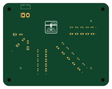
Earlier revisions in the repo: PNP_MOBO_V1
Similar boards
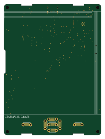 ESP32
OSO-BOOK-B1
joeycastillo
85 × 115 mm65 parts2LCC-BY-SA-4.08.1k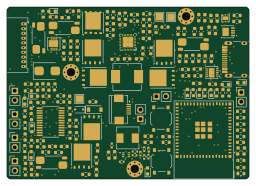 ESP32
Powertrain
byrantech
64 × 45.4 mm171 parts4LMIT4.3k ESP32
Badge
atopile
56.3 × 39 mm239 parts4LMIT4.0k ESP32
Esp32 minimal
36.2 × 26.8 mm20 parts2LMIT4.0k ESP32
Controller
StuckAtPrototype
29 × 74 mm58 parts4LApache-2.03.8k ESP32
Racer
36 × 50.2 mm70 parts4LApache-2.03.8k