
EPC Breakout

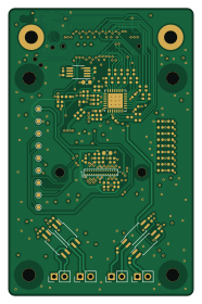
About the EPC Breakout
EPC Breakout is an open source AVR/Arduino PCB design by gregdavill, published on GitHub. It is a 4-layer board measuring 45 × 70 mm, with 97 components from 25 distinct parts.
Its main chip is the ATTINY44A-MMH, from the AVR/Arduino family. Other key parts include the AD9629BCPZ-65, EPC901-CSP32-033, LT1962EMS8-1.8#PBF and TLP291(GB-TP,SE. By type, the board carries 55 resistors, 26 capacitors, 8 ICs, 6 connectors and 1 inductor.
It belongs with the dev boards & breakouts designs in this gallery.
From the project
1 circuit board design a day for 31 days.
SYZYGY is an FPGA expansion standard for medium to high speed interfaces. Learn more and check out the specifications here: https://syzygyfpga.io/
Based on the breakout from astuder (https://github.com/astuder/epc901)
The EPC901 is a 1024x1 CCD sensor, this sensor capable of 50MHz pixel output. It outputs an analog voltage from the CCD elements. So I've paired it with a 50MSps ADC on a SYZYGY board. The datasheet claims it can run upto 50k fps.
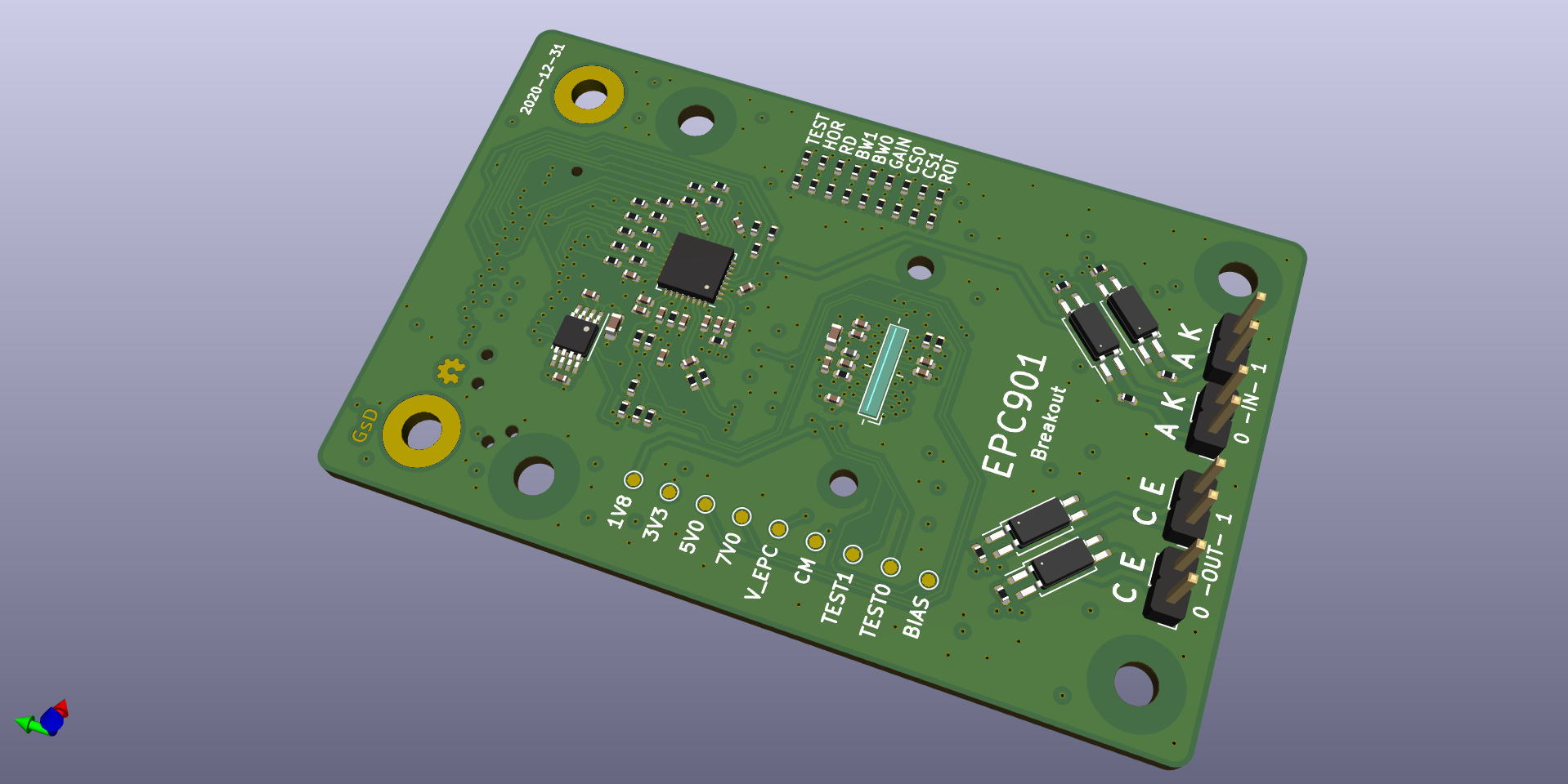
Main components on the EPC Breakout
EPC Breakout bill of materials (BOM)
97 components, 25 distinct parts.
| Qty | Part | Footprint | Refs |
|---|---|---|---|
| 1 | AD9629BCPZ-65 AD9629 | QFN-32-1EP_5x5mm_P0.5mm_EP3.6x3.6mm_ThermalVias | U1 |
| 1 | ATTINY44A-MMH ATtiny44A-MMH | QFN-20-1EP_3x3mm_P0.45mm_EP1.6x1.6mm | U2 |
| 1 | EPC901-CSP32-033 EPC901 | epc901 | U3 |
| 1 | LT1962EMS8-1.8#PBF LT1962-1.8 | MSOP-8_3x3mm_P0.65mm | U4 |
| 4 | TLP291(GB-TP,SE TLP291 | SOIC-4_4.55x2.6mm_P1.27mm | U5, U6, U7, U8 |
| 1 | QTE-020-01-F-D-A-K SYZYGY-STD | SYZYGY-STD-POD | J1 |
| 4 | Conn_01x02_Male | PinHeader_1x02_P2.54mm_Vertical | J2, J4, J5, J6 |
| 1 | TagConnect | TC2030-NL_SMALL | J3 |
| 1 | LensMount | lensholder-m12-20mm | H5 |
| 1 | BLM15HG601SN1D 600R @100M | L_0402_1005Metric | L1 |
| 11 | CC0402JRX7R7BB104 0.1uF | C_0402_1005Metric | C1, C4, C5, C9, C11, C20, C21, C22 +3 |
| 8 | CC0402KRX5R8BB105 1uF | C_0402_1005Metric | C2, C6, C7, C10, C13, C16, C19, C25 |
| 1 | CC0402JRNPO9BN220 22pF | C_0402_1005Metric | C3 |
| 2 | CC0603KRX5R5BB106 10uF | C_0603_1608Metric | C8, C18 |
| 1 | DNP | C_0402_1005Metric | C12 |
| 2 | CC0402KRX5R6BB225 2.2uF | C_0402_1005Metric | C14, C15 |
| 1 | CC0402JRX7R9BB103 0.01uF | C_0402_1005Metric | C17 |
| 17 | DNP | R_0402_1005Metric | R1, R11, R12, R13, R14, R16, R17, R18 +9 |
| 5 | AC0402FR-070RL 0R | R_0402_1005Metric | R2, R23, R24, R25, R32 |
| 2 | AC0402FR-0733RL 33R | R_0402_1005Metric | R3, R4 |
Show 5 more
| Qty | Part | Footprint | Refs |
|---|---|---|---|
| 22 | AC0402FR-07100RL 100R | R_0402_1005Metric | R5, R6, R7, R8, R35, R36, R37, R38 +14 |
| 4 | AC0402FR-072K2L 2K2 | R_0402_1005Metric | R9, R10, R50, R51 |
| 2 | AC0402FR-0710KL 10K | R_0402_1005Metric | R15, R49 |
| 1 | AC0402FR-0756KL 56K 1% 100ppm/K | R_0402_1005Metric | R22 |
| 2 | AC0402FR-071KL 1K | R_0402_1005Metric | R33, R34 |
EPC Breakout design files
The KiCad project lives in the gregdavill/advent-calendar-of-circuits-2020 repository on GitHub; these links point at the commit this page was built from.
EPC Breakout: common questions
What microcontroller does the EPC Breakout use?
The EPC Breakout is built around the ATTINY44A-MMH, from the AVR/Arduino family.
How big is the EPC Breakout?
The EPC Breakout measures 45 × 70 mm, has 4 copper layers and is 1.6 mm thick.
How many components are on the EPC Breakout?
97 components, from 25 distinct parts. The full bill of materials is listed on this page.
Where can I download the EPC Breakout design files?
From the gregdavill/advent-calendar-of-circuits-2020 repository on GitHub, which has the KiCad layout and the schematic; the links under Design files point to each one.
Can I use the EPC Breakout design in my own project?
The repository has no license, so all rights stay with gregdavill. Use it as a reference, and ask the author before reusing the design.
Can I test firmware for the EPC Breakout without the hardware?
Yes. HardLabs builds a simulation of the board from its netlist and BOM, so you can run and debug AVR/Arduino firmware against it before you order a PCB.
More boards in advent-calendar-of-circuits-2020
 FPGA
ECPBreaker
50 × 37 mm117 parts6LNo license178 FPGA
ICEBreaker+++
56 × 37 mm104 parts4LNo license178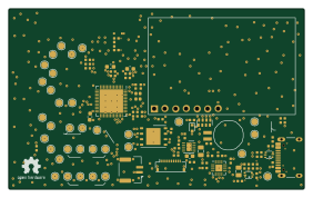 ESP32
Esp32s2-co2-monitor
70.3 × 42.8 mm67 parts4LNo license178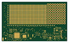 ESP32
ESP32S2 Breakout
70.3 × 42.8 mm64 parts4LNo license178 ESP32
Esp32s2-lepton
34.6 × 30.8 mm62 parts4LNo license178 Microchip SAM
Meiji Led Ring
64 × 64 mm61 parts4LNo license178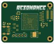 FPGA
Resonance
45 × 35.5 mm60 parts4LNo license178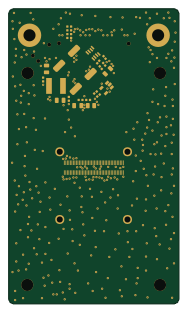 AVR/Arduino
Boson Breakout
45 × 78 mm35 parts4LNo license178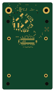 AVR/Arduino
Tau2 Breakout
45 × 78 mm32 parts4LNo license178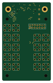 AVR/Arduino
SYZYGY SGMII
50 × 80 mm31 parts4LNo license178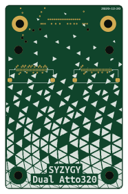 AVR/Arduino
Dual Atto320 breakout
45 × 70 mm8 parts4LNo license178
Similar boards
 AVR/Arduino
Magspoof
samyk
35 × 29 mm11 parts2LNo license4.2k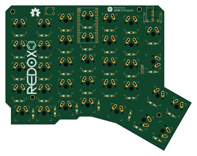 AVR/Arduino
Redox keyboard
mattdibi
162.2 × 126.5 mm77 parts2LMIT2.0k AVR/Arduino
Labrador
espotek-org
36.8 × 34.7 mm75 parts2LNo license1.2k AVR/Arduino
V4
stuartpittaway
30 × 50 mm38 parts2LCC-BY-NC-4.01.1k AVR/Arduino
ModuleV450
30 × 61.4 mm39 parts2LCC-BY-NC-4.01.1k AVR/Arduino
Discipline
coseyfannitutti
304.9 × 122.8 mm170 parts2LCC-BY-NC-4.01.0k