
ICEBreaker+++

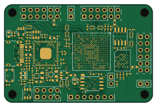
About the ICEBreaker+++ PCB
ICEBreaker+++ is an open source FPGA PCB design by gregdavill, published on GitHub. It is a 4-layer board measuring 56 × 37 mm, with 104 components from 46 distinct parts.
Its main chip is the LFE5U-12F-8BG256C, from the FPGA family. Other key parts include the 93LC46BT-I/OT, FT2232HQ-TRAY, W25Q32JVSSIQ TR, TLV62569DRLR and TLV713285PDBVR. By type, the board carries 43 capacitors, 27 resistors, 14 connectors, 10 ICs, 5 diodes and 4 inductors.
From the project
1 circuit board design a day for 31 days.
The icebreaker is a friendly development board for the iCE40: https://github.com/icebreaker-fpga/icebreaker
The icebreaker is a really nice and handy little board. But it has a small flaw, the ice40 FPGA it uses is quite smol, while it's often fun to see the exciting projects people pull off with 5k LUTs. Sometimes it's handy to have a bit of extra space available whe experimenting.
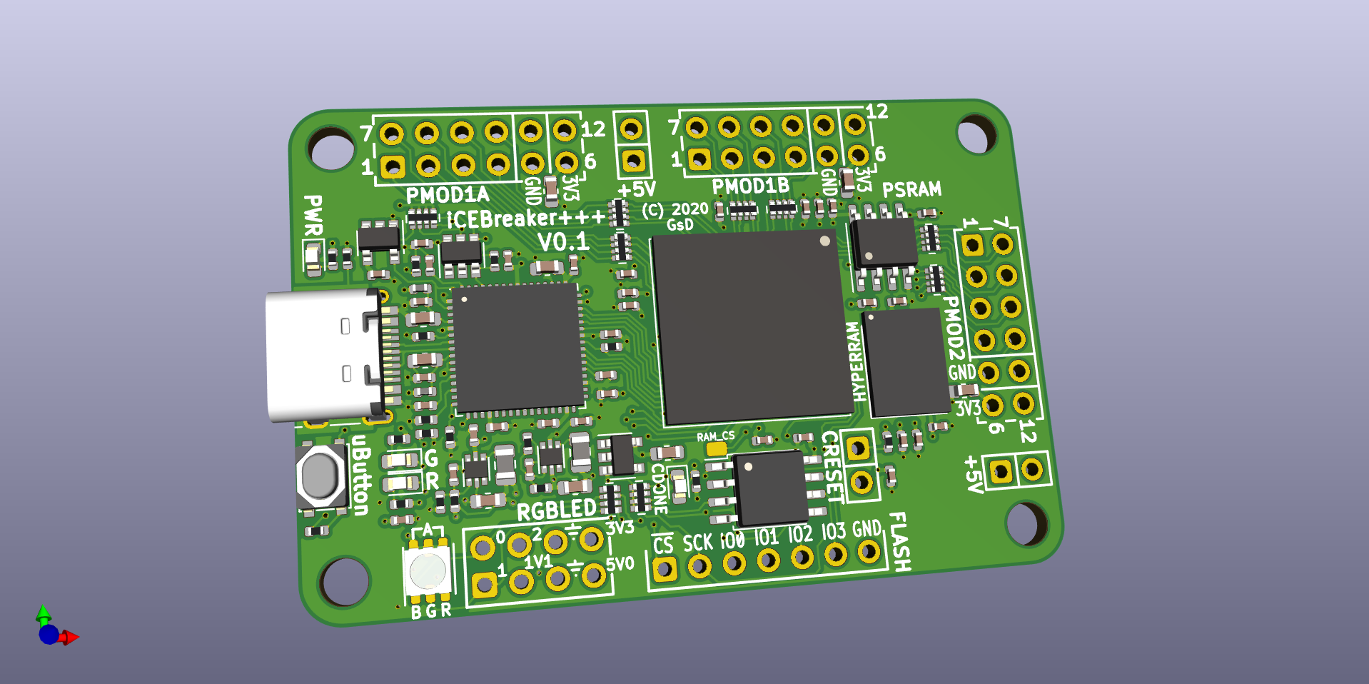
Main components on the ICEBreaker+++
ICEBreaker+++ bill of materials (BOM)
104 components, 46 distinct parts.
| Qty | Part | Footprint | Refs |
|---|---|---|---|
| 1 | 93LC46BT-I/OT 93C46B-SOT-23-6 | SOT-23-6 | U1 |
| 1 | FT2232HQ-TRAY FT2232H | QFN-64-1EP_9x9mm_P0.5mm_EP4.35x4.35mm | U2 |
| 1 | W25Q32JVSSIQ TR W25Q32JVSS | SOIC-8_5.23x5.23mm_P1.27mm | U3 |
| 2 | TLV62569DRLR TLV62569DRL | SOT-666 | U4, U5 |
| 1 | TLV713285PDBVR TLV713285PDBV | SOT-23-5 | U6 |
| 1 | SIT2001BI-S2-33E-12.000000G 12MHz | SOT-23-5 | U7 |
| 1 | LFE5U-12F-8BG256C ECP5U-12-CABGA256 | BGA-256_14.0x14.0mm_Layout16x16_P0.8mm_Ball0.45mm_Pad0.32mm_NSMD | U8 |
| 1 | LY68L6400SLIT | SOIC-8_3.9x4.9mm_P1.27mm | U9 |
| 1 | IS66WVH16M8ALL-166B1LI IS66WVH16M8ALL | BGA-24_8.0x6.0mm_Layout5x5_P0.8mm_Pad0.35mm_NSMD | U10 |
| 1 | Flash | PinHeader_1x07_P2.54mm_Vertical | J20 |
| 3 | PMOD | PMOD_Angled_2x06 | J21, J23, J27 |
| 2 | 5V AUX | PinHeader_2x01_P2.54mm_Vertical | J22, J26 |
| 1 | USB_C_Receptacle_USB2.0 | USB_C_Receptacle_HRO_TYPE-C-31-M-12 | J24 |
| 1 | RGB Led | PinHeader_2x04_P2.54mm_Vertical | J25 |
| 1 | CRESET | PinHeader_2x01_P2.54mm_Vertical | J28 |
| 4 | UP | PAD_SMD_1x2.65 | P2, P3, P4, P5 |
| 1 | RAM_CS | PAD_SMD_1x1.5 | P6 |
| 1 | PTS810SJK250SMTRLFS TACT | SW_SPST_PTS810 | SW1 |
| 2 | SML-D12P8WT86 GRN | LED_0603_1608Metric | D1, D4 |
| 1 | SMLD12BN1WT86 BLU | LED_0603_1608Metric | D3 |
Show 26 more
| Qty | Part | Footprint | Refs |
|---|---|---|---|
| 1 | SML-D12V8WT86 RED | LED_0603_1608Metric | D5 |
| 1 | CLY6D-FKC-CNP1ST1E1BB7D3D3 LED_RGB Cree | LED_Cree_PLCC6_3.4x3.4mm | D11 |
| 2 | 600 | L_0402_1005Metric | L1, L2 |
| 2 | SLM20122R2MIT 2.2uH | L_0805_2012Metric | L3, L4 |
| 13 | C0402C104K8PAC7411 100n | C_0402_1005Metric | C1, C4, C10, C12, C13, C14, C16, C17 +5 |
| 10 | C0402C104K8PAC7411 0.1uF | C_0402_1005Metric | C2, C3, C5, C8, C11, C39, C40, C41 +2 |
| 3 | 4u7 | C_0603_1608Metric | C6, C7, C9 |
| 2 | CC0402KRX5R6BB475 4.7uF | C_0402_1005Metric | C15, C23 |
| 3 | CC0603KRX5R5BB106 10uF | C_0603_1608Metric | C24, C28, C29 |
| 3 | CC0402KRX5R6BB105 1uF | C_0402_1005Metric | C25, C30, C31 |
| 2 | CC0402CRNPO9BN6R8 6.8pF | C_0402_1005Metric | C26, C27 |
| 3 | DNP | C_0603_1608Metric | C32, C33, C34 |
| 4 | CC0402KRX5R6BB105 0.1uF | C_0402_1005Metric | C35, C36, C37, C38 |
| 1 | MCS04020C1004FE000 1M | R_0402_1005Metric | R1 |
| 2 | EXB-28V103JX 10k | R_Array_Convex_4x0402 | R2, R11 |
| 7 | 33R | R_Array_Convex_4x0402 | R3, R4, R7, R16, R17, R18, R27 |
| 3 | RC0402FR-07330RL 330E | R_0402_1005Metric | R5, R14, R15 |
| 2 | RC0402FR-072K2L 2k2 | R_0402_1005Metric | R6, R12 |
| 1 | RC0402FR-0712KL 12k | R_0402_1005Metric | R8 |
| 4 | RC0402FR-0710KL 10k | R_0402_1005Metric | R9, R13, R19, R25 |
| 1 | RC0402FR-07210KL 210k | R_0402_1005Metric | R10 |
| 1 | RT0402FRE071KL 1k | R_0402_1005Metric | R20 |
| 2 | AF0402JR-075K1L 5.1k | R_0402_1005Metric | R21, R22 |
| 1 | RC0402FR-0747KL 47k | R_0402_1005Metric | R23 |
| 1 | RC0402FR-0784K5L 84k5 | R_0402_1005Metric | R24 |
| 1 | RC0402FR-07100KL 100k | R_0402_1005Metric | R26 |
ICEBreaker+++ design files
The KiCad project lives in the gregdavill/advent-calendar-of-circuits-2020 repository on GitHub; these links point at the commit this page was built from.
ICEBreaker+++: common questions
What microcontroller does the ICEBreaker+++ use?
The ICEBreaker+++ is built around the LFE5U-12F-8BG256C, from the FPGA family.
How big is the ICEBreaker+++ PCB?
The ICEBreaker+++ measures 56 × 37 mm, has 4 copper layers and is 1.6 mm thick.
How many components are on the ICEBreaker+++?
104 components, from 46 distinct parts. The full bill of materials is listed on this page.
Where can I download the ICEBreaker+++ design files?
From the gregdavill/advent-calendar-of-circuits-2020 repository on GitHub, which has the KiCad layout and the schematic; the links under Design files point to each one.
Can I use the ICEBreaker+++ design in my own project?
The repository has no license, so all rights stay with gregdavill. Use it as a reference, and ask the author before reusing the design.
Can I test firmware for the ICEBreaker+++ without the hardware?
Yes. HardLabs builds a simulation of the board from its netlist and BOM, so you can run and debug FPGA firmware against it before you order a PCB.
More boards in advent-calendar-of-circuits-2020
 FPGA
ECPBreaker
50 × 37 mm117 parts6LNo license178 AVR/Arduino
EPC Breakout
45 × 70 mm97 parts4LNo license178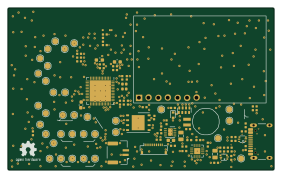 ESP32
Esp32s2-co2-monitor
70.3 × 42.8 mm67 parts4LNo license178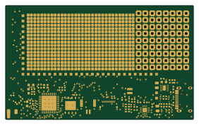 ESP32
ESP32S2 Breakout
70.3 × 42.8 mm64 parts4LNo license178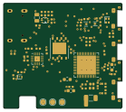 ESP32
Esp32s2-lepton
34.6 × 30.8 mm62 parts4LNo license178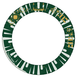 Microchip SAM
Meiji Led Ring
64 × 64 mm61 parts4LNo license178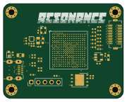 FPGA
Resonance
45 × 35.5 mm60 parts4LNo license178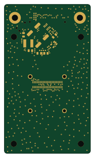 AVR/Arduino
Boson Breakout
45 × 78 mm35 parts4LNo license178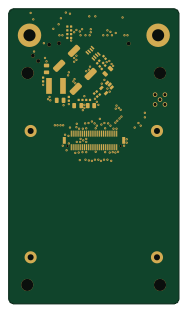 AVR/Arduino
Tau2 Breakout
45 × 78 mm32 parts4LNo license178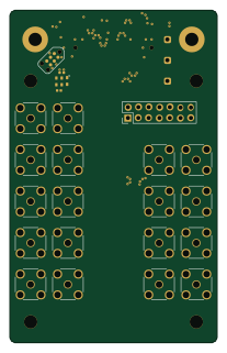 AVR/Arduino
SYZYGY SGMII
50 × 80 mm31 parts4LNo license178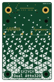 AVR/Arduino
Dual Atto320 breakout
45 × 70 mm8 parts4LNo license178
Similar boards
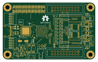 FPGA
Base board
GlasgowEmbedded
80 × 49 mm222 parts4L0BSD2.2k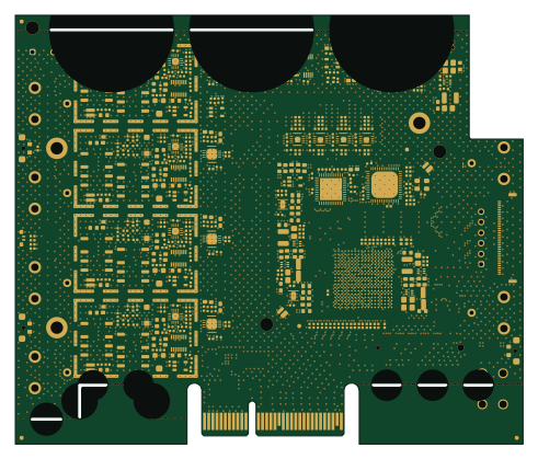 FPGA
Thunderscope Rev5.3
EEVengers
122.5 × 103.5 mm817 parts6LMIT1.3k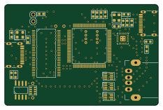 FPGA
Usb sniffer
ataradov
58.2 × 38.1 mm86 parts2LBSD-3-Clause1.3k FPGA
Tomu, I'm
theacodes
13 × 9.4 mm40 parts4LMIT1.1k FPGA
Icepi zero
cheyao
65 × 30 mm143 parts4LSHL-2.1828 FPGA
Gcvideo
ikorb
49 × 30 mm44 parts4LNo license765