
IoT-Enabled-WiFi-Router-UPS

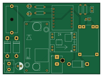
About the IoT-Enabled-WiFi-Router-UPS PCB
IoT-Enabled-WiFi-Router-UPS is an open source PCB design by HarshBotre, published on GitHub. It is a 4-layer board measuring 81.8 × 60.4 mm, with 19 components from 15 distinct parts.
Other key parts include the XIAO_ESP32C3, TP4056_MICRO-USB_CHARGER_-_1A, KL6009 and MP1584EN. By type, the board carries 5 diodes, 4 ICs, 4 resistors, 2 connectors, 2 capacitors and 1 battery holder.
It belongs with the power & battery and iot & wireless designs in this gallery.
From the project
A custom PCB uninterruptible power supply and network diagnostic node using ESP32-C3.
A custom 2-layer PCB designed to provide seamless battery backup for a 12V WiFi router, featuring an onboard ESP32-C3 microcontroller for live network health diagnostics and battery telemetry.
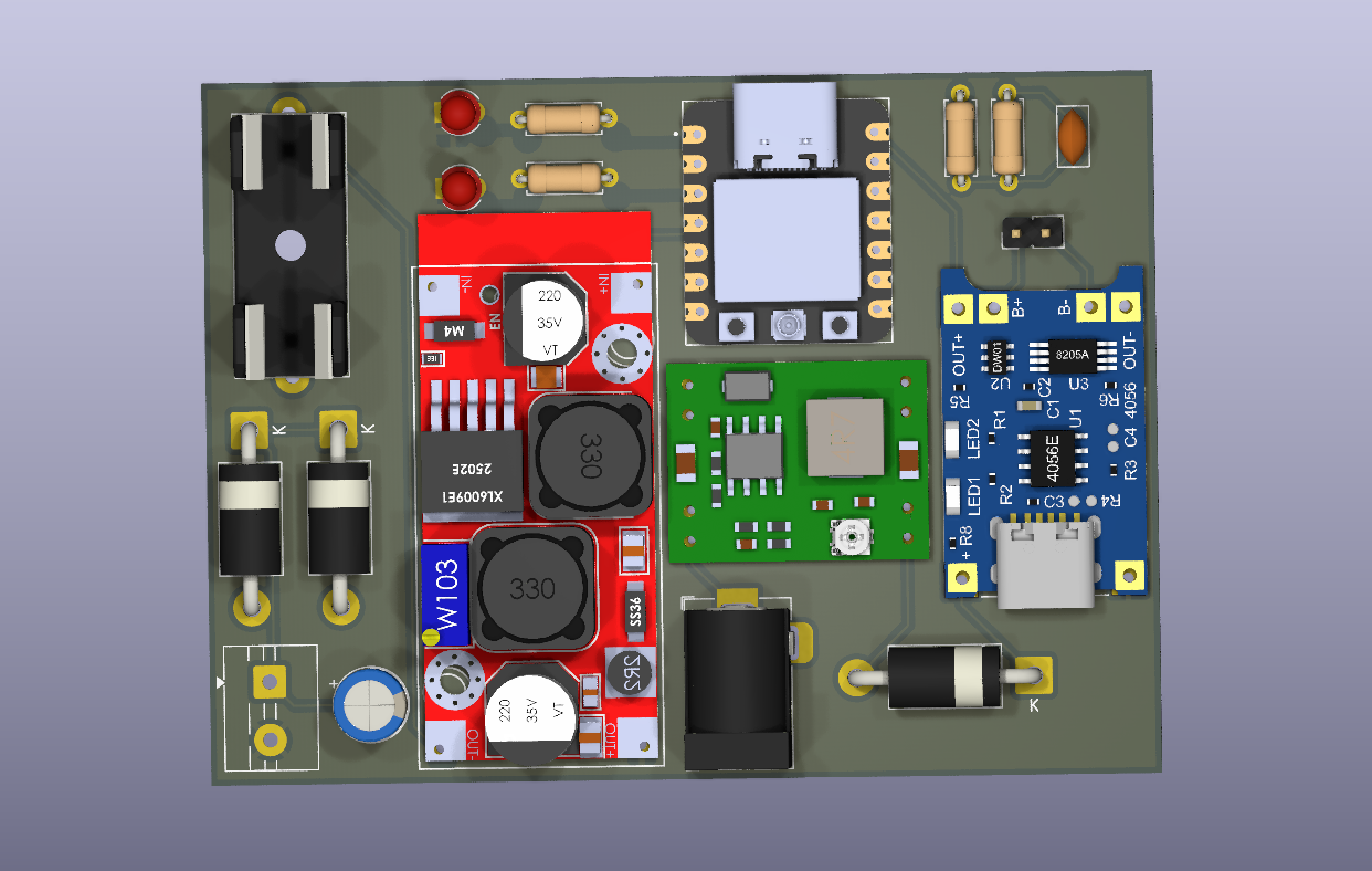
Main components on the IoT-Enabled-WiFi-Router-UPS
IoT-Enabled-WiFi-Router-UPS bill of materials (BOM)
19 components, 15 distinct parts.
| Qty | Part | Footprint | Refs |
|---|---|---|---|
| 1 | XIAO_ESP32C3 | MODULE_XIAO_ESP32C3 | U1 |
| 1 | TP4056_MICRO-USB_CHARGER_-_1A | MODULE_TP4056_MICRO-USB_CHARGER_-_1A | U2 |
| 1 | KL6009 | XL6009_module | U3 |
| 1 | MP1584EN | MP1584_buck_module | U4 |
| 1 | F Barrel-Jack | BarrelJack_Horizontal | J1 |
| 1 | Screw_Terminal_01x02 | TerminalBlock_MaiXu_MX126-5.0-02P_1x02_P5.00mm | J2 |
| 1 | Battery | PinHeader_1x02_P2.54mm_Vertical | BT1 |
| 1 | Fuse | Fuseholder_Cylinder-5x20mm_Schurter_0031_8201_Horizontal_Open | F1 |
| 3 | 1N5822 | D_DO-201AD_P15.24mm_Horizontal | D1, D2, D3 |
| 2 | LED | LED_D3.0mm | D4, D5 |
| 1 | 100 | C_Disc_D5.0mm_W2.5mm_P2.50mm | C1 |
| 1 | 470 C_Polarized | CP_Radial_D6.3mm_P2.50mm | C2 |
| 2 | 220 | R_Axial_DIN0207_L6.3mm_D2.5mm_P7.62mm_Horizontal | R1, R2 |
| 1 | 100 | R_Axial_DIN0207_L6.3mm_D2.5mm_P7.62mm_Horizontal | R3 |
| 1 | 33 | R_Axial_DIN0207_L6.3mm_D2.5mm_P7.62mm_Horizontal | R4 |
IoT-Enabled-WiFi-Router-UPS design files
The KiCad project lives in the HarshBotre/IoT-Enabled-WiFi-Router-UPS repository on GitHub; these links point at the commit this page was built from.
- LayoutHardware/WIFI UPS.kicad_pcb
- SchematicHardware/WIFI UPS.kicad_sch
IoT-Enabled-WiFi-Router-UPS: common questions
How big is the IoT-Enabled-WiFi-Router-UPS PCB?
The IoT-Enabled-WiFi-Router-UPS measures 81.8 × 60.4 mm, has 4 copper layers and is 1.600198 mm thick.
How many components are on the IoT-Enabled-WiFi-Router-UPS?
19 components, from 15 distinct parts. The full bill of materials is listed on this page.
Where can I download the IoT-Enabled-WiFi-Router-UPS design files?
From the HarshBotre/IoT-Enabled-WiFi-Router-UPS repository on GitHub, which has the KiCad layout and the schematic; the links under Design files point to each one.
Can I use the IoT-Enabled-WiFi-Router-UPS design in my own project?
The repository has no license, so all rights stay with HarshBotre. Use it as a reference, and ask the author before reusing the design.
Similar boards

EinkPDA screen
TalismanDesign
95 × 54 mm27 parts2LApache-2.02.0k
Stack chan
stack-chan
50 × 50 mm33 parts2LApache-2.01.7k
Display Carrier
AxxAxx
35.6 × 58.2 mm5 parts2LGPL-3.01.7k
Module 16S PassiveBalanceAddOn
stuartpittaway
61 × 74 mm86 parts2LCC-BY-NC-4.01.1k
TemperaturePCB PANEL
116 × 75.5 mm178 parts2LCC-BY-NC-4.01.1k
ProgrammingAdapter
10.5 × 83 mm3 parts2LCC-BY-NC-4.01.1k