
Stm32-fpga oscilloscope

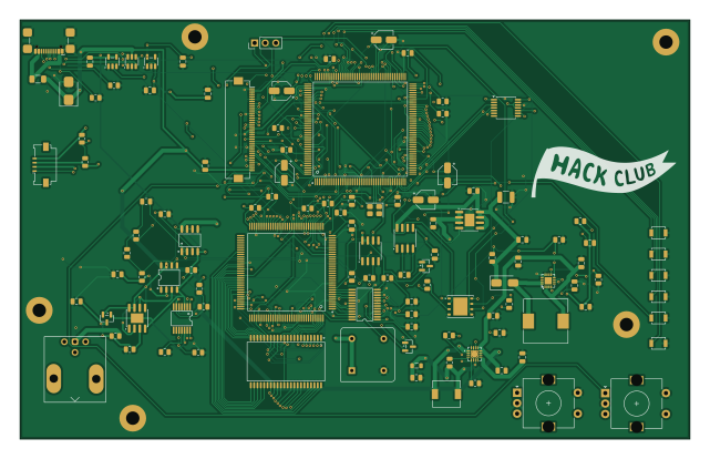
About the Stm32-fpga oscilloscope PCB
Stm32-fpga oscilloscope is an open source STM32 PCB design by HexFud, published on GitHub. It is a 4-layer board measuring 160 × 100 mm, with 115 components from 66 distinct parts.
Its main chip is the LQFP-176_L24.0-W24.0-P0.50-LS26.0-BL, from the STM32 family. Other key parts include the MCP4922, TLV3501AID, W25Q128JVP, TPS62130 and LT1054. By type, the board carries 39 capacitors, 34 resistors, 18 ICs, 8 switches, 5 diodes and 3 connectors.
It belongs with the test & measurement and displays & leds designs in this gallery.
From the project
A 1-Channel 20MHz 100MS/s Mixed-Signal Digital Storage Oscilloscope on a custom 4-layer PCB. Powered by STM32H7, Lattice iCE40 FPGA, and USB-C
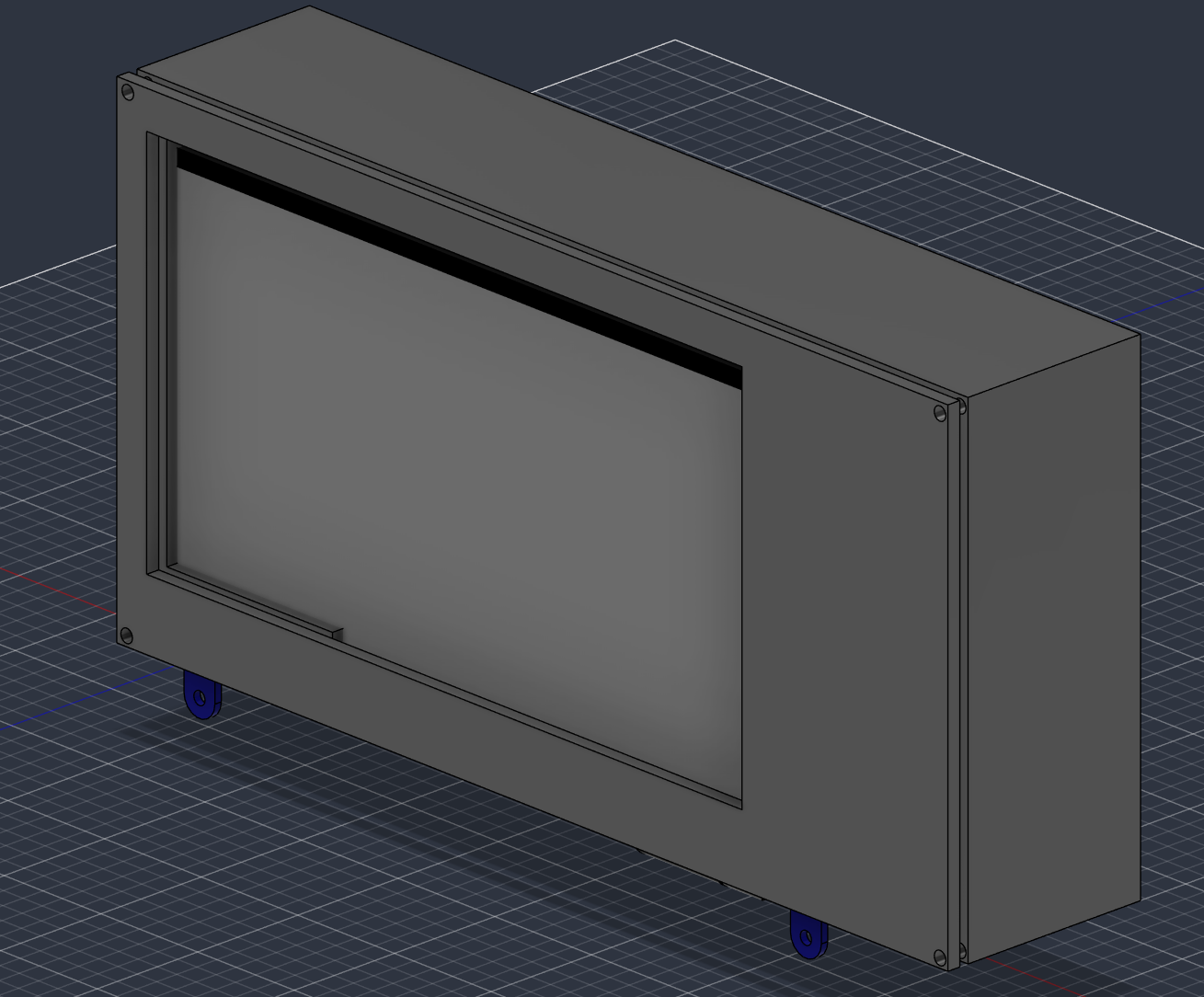
The project is made of three parts that were designed together, because each one constrains the others: the PCB decides what the firmware can do, and the heat generated on the PCB decides how the enclosure is built.
I have designed the PCB starting from an STM32H7 microcontroller because of its support for external SRAM and it can directly control the main 7 Inch display with high speed transmission data. The entire board runs using a single 5V usb-C connection and then internally this becomes 3.3V, 1.2V and ±5V. The board includes connections for: - A standard BNC input for oscilloscope…
Main components on the Stm32-fpga oscilloscope
Stm32-fpga oscilloscope bill of materials (BOM)
115 components, 66 distinct parts.
| Qty | Part | Footprint | Refs |
|---|---|---|---|
| 1 | MCP4922 | TSSOP-14_4.4x5mm_P0.65mm | U1 |
| 1 | ~ TI(德州仪器) | QFN-16_L3.0-W3.0-P0.50-BL-EP1.7 | U2 |
| 1 | TLV3501AID | SOIC-8_3.9x4.9mm_P1.27mm | U3 |
| 1 | ~ LATTICE(莱迪思) | TQFP-144_L20.0-W20.0-P0.50-LS22.0-BL | U4 |
| 1 | ~ | TSSOP-24_L7.8-W4.4-P0.65-LS6.4-BL | U5 |
| 1 | W25Q128JVP | WSON-8-1EP_6x5mm_P1.27mm_EP3.4x4.3mm | U6 |
| 1 | ~ ST(意法半导体) | LQFP-176_L24.0-W24.0-P0.50-LS26.0-BL | U7 |
| 1 | TPS62130 | VQFN-16-1EP_3x3mm_P0.5mm_EP1.68x1.68mm_ThermalVias | U8 |
| 1 | LT1054 | SOIC-8_3.9x4.9mm_P1.27mm | U9 |
| 1 | ADP7142ARDZ | SOIC-8-1EP_3.9x4.9mm_P1.27mm_EP2.29x3mm | U10 |
| 1 | ADP7182AUJZ | TSOT-23-5 | U11 |
| 1 | IS61WV25616BLL-10TLI ISSI(北京矽成) | TSOP-44_L18.4-W10.2-P0.80-LS11.8-BL | U13 |
| 1 | USBLC6-2SC6 | SOT-23-6 | U14 |
| 1 | ADA4817-1ARD | SOIC-8-1EP_3.9x4.9mm_P1.27mm_EP2.29x3mm | U15 |
| 1 | AP2112K-1.2 | SOT-23-5 | U16 |
| 1 | ~ | SOP-8_L4.9-W3.9-P1.27-LS6.0-TL | U17 |
| 1 | ~ ADI(亚德诺) | TSSOP-14_L5.0-W4.4-P0.65-LS6.4-BL | U18 |
| 1 | ~ ADI(亚德诺) | SOP-8_L4.9-W3.9-P1.27-LS6.0-BL | U19 |
| 1 | CXO_DIP8 | Oscillator_DIP-8 | Y1 |
| 1 | 8Mhz | Crystal_SMD_3225-4Pin_3.2x2.5mm | Y5 |
Show 46 more
| Qty | Part | Footprint | Refs |
|---|---|---|---|
| 1 | Conn_01x03_Pin | PinHeader_1x03_P2.54mm_Vertical | J1 |
| 1 | Conn_Coaxial | BNC_Amphenol_031-6575_Horizontal | J2 |
| 1 | USB_C_Plug | USB_C_Receptacle_GCT_USB4110 | P1 |
| 1 | Fuse | Fuse_1206_3216Metric | F1 |
| 1 | Conn_01x40_Socket | Hirose_FH12-40S-0.5SH_1x40-1MP_P0.50mm_Horizontal | LCD_CONNECTOR1 |
| 2 | RotaryEncoder_Switch | RotaryEncoder_Alps_EC11E-Switch_Vertical_H20mm | SW1, SW2 |
| 6 | SW_Push | SW_SPST_B3U-1000P | SW9, SW10, SW11, SW12, SW13, SW14 |
| 1 | Conn_01x04_Socket | Molex_200528-0040_1x04-1MP_P1.00mm_Horizontal | TOUCH_CONNECTOR1 |
| 1 | BAV99 | SOT-23 | D1 |
| 2 | BAT54S | SOT-23 | D2, D5 |
| 1 | 550mV | D_SMA | D3 |
| 1 | D_Schottky | D_SMB | D4 |
| 1 | FerriteBead | L_0805_2012Metric | FB1 |
| 1 | 2.2uH | L_6.3x6.3_H3 | L1 |
| 1 | 2.2uH | L_10.4x10.4_H4.8 | L2 |
| 8 | 100nF | C_0805_2012Metric | C1, C5, C12, C25, C34, C35, C36, C39 |
| 9 | 10uF | C_0805_2012Metric | C2, C6, C13, C14, C15, C26, C27, C28 +1 |
| 1 | 22uF | C_0805_2012Metric | C3 |
| 1 | 390pF | C_0805_2012Metric | C4 |
| 1 | 10uF | C_1210_3225Metric | C7 |
| 3 | 1uF | C_0805_2012Metric | C8, C16, C17 |
| 1 | 270nF | C_0805_2012Metric | C9 |
| 1 | 4.7nF | C_0805_2012Metric | C10 |
| 1 | 56nF | C_0805_2012Metric | C11 |
| 5 | 100nF | CP_Elec_4x5.4 | C18, C19, C20, C21, C22 |
| 1 | 30pF | C_0805_2012Metric | C23 |
| 1 | 47pF | C_0805_2012Metric | C24 |
| 2 | 12pF | C_0805_2012Metric | C29, C30 |
| 2 | 2.2uF | C_0805_2012Metric | C31, C32 |
| 1 | 22pF | C_0805_2012Metric | C33 |
| 1 | 2.2pF | C_0805_2012Metric | C38 |
| 4 | 100 | R_0805_2012Metric | R1, R21, R26, R27 |
| 2 | 5.1k | R_0805_2012Metric | R2, R10 |
| 2 | 100K | R_0805_2012Metric | R3, R24 |
| 1 | 562K | R_0805_2012Metric | R4 |
| 1 | 180K | R_0805_2012Metric | R5 |
| 1 | 47k | R_0805_2012Metric | R6 |
| 10 | 10k | R_0805_2012Metric | R7, R13, R14, R18, R19, R23, R25, R32 +2 |
| 3 | 1k | R_0805_2012Metric | R8, R15, R22 |
| 1 | 32.4k | R_0805_2012Metric | R9 |
| 1 | 220 | R_0805_2012Metric | R11 |
| 1 | 1M | R_0805_2012Metric | R12 |
| 4 | 4,7K | R_0805_2012Metric | R16, R17, R30, R31 |
| 1 | 47 | R_0805_2012Metric | R20 |
| 1 | 150 | R_0805_2012Metric | R28 |
| 1 | 374 | R_0805_2012Metric | R29 |
Stm32-fpga oscilloscope design files
The KiCad project lives in the HexFud/stm32-fpga-oscilloscope repository on GitHub; these links point at the commit this page was built from.
- LayoutPCB/Hex_Oscilloscope.kicad_pcb
- SchematicPCB/Hex_Oscilloscope.kicad_sch
Stm32-fpga oscilloscope: common questions
What microcontroller does the Stm32-fpga oscilloscope use?
The Stm32-fpga oscilloscope is built around the LQFP-176_L24.0-W24.0-P0.50-LS26.0-BL, from the STM32 family.
How big is the Stm32-fpga oscilloscope PCB?
The Stm32-fpga oscilloscope measures 160 × 100 mm, has 4 copper layers and is 1.6 mm thick.
How many components are on the Stm32-fpga oscilloscope?
115 components, from 66 distinct parts. The full bill of materials is listed on this page.
Where can I download the Stm32-fpga oscilloscope design files?
From the HexFud/stm32-fpga-oscilloscope repository on GitHub, which has the KiCad layout and the schematic; the links under Design files point to each one.
Can I use the Stm32-fpga oscilloscope design in my own project?
The repository has no license, so all rights stay with HexFud. Use it as a reference, and ask the author before reusing the design.
Can I test firmware for the Stm32-fpga oscilloscope without the hardware?
Yes. HardLabs builds a simulation of the board from its netlist and BOM, so you can run and debug STM32 firmware against it before you order a PCB.
Similar boards
 STM32
LumenPnP Motherboard
opulo-inc
149 × 95 mm296 parts4LCC-BY-SA-4.03.7k STM32
Base
google
52.3 × 52.3 mm36 parts2LApache-2.02.9k STM32
Main panel
234 × 84 mm26 parts4LApache-2.02.9k STM32
Type g
169 × 30 mm24 parts2LApache-2.02.9k STM32
Type a
150 × 30 mm14 parts2LApache-2.02.9k STM32
Type c
188 × 30 mm17 parts2LApache-2.02.9k