
Smd board

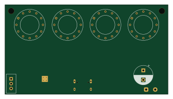
About the Smd board
Smd board is an open source RP2040/RP2350 PCB design by hinatadayo, published on GitHub. It is a 4-layer board measuring 86 × 47 mm, with 112 components from 32 distinct parts.
Its main chip is the RP2040, from the RP2040/RP2350 family. Other key parts include the AMS1117-3.3, W25Q16JVSSIQ and USBLC6-2SC6. By type, the board carries 20 capacitors, 12 resistors, 4 ICs, 2 connectors, 1 transistor and 1 crystal.
It belongs with the displays & leds designs in this gallery.
From the project
nixie-token-display-schematic.md(Rev 0.2)に基づく 3 枚基板構成。 回路図・基板ともに Python (kiutils + 直接 S 式生成) でプログラム生成している。
nixie-token-display-schematic.md(Rev 0.2)に基づく 3 枚基板構成。 回路図・基板ともに Python (kiutils + 直接 S 式生成) でプログラム生成している。
分け方の制約はカソードバスにある。カソードは全桁で共有するので桁ごとの基板には できず、かといって管と同居させると 1 枚が大きくなりすぎる。だからカソードドライバだけ 独立させた。
カソード 10 本が全部 200V ネットで、1 本あたり 1.3mm の通り道が要る (線幅 0.3mm + クリアランス 1mm)。この 10 本は全部の管に行くので、 管 1 本の脇を必ず 10 本とも通過する。管どうしの隙間は ピッチ − 15.1mm:
4 桁が、管基板を 100×100 に収められる最大の桁数。 仕様書 1 章の 3 モード (残量 %、トークン数、リセットまでの時間)はいずれも 4 桁で表現できる。 6 桁にするなら 4 層化するか沿面 1mm を緩めることになり、どちらも設計判断。
Main components on the Smd board
Smd board bill of materials (BOM)
112 components, 32 distinct parts.
| Qty | Part | Footprint | Refs |
|---|---|---|---|
| 1 | RP2040 | QFN-56-1EP_7x7mm_P0.4mm_EP3.2x3.2mm_Via0.3 | U1 |
| 1 | AMS1117-3.3 | SOT-223-3_TabPin2 | U2 |
| 1 | W25Q16JVSSIQ | SOIC-8_3.9x4.9mm_P1.27mm | U3 |
| 1 | USBLC6-2SC6 | SOT-23-6 | U4 |
| 1 | MMBT3904 | SOT-23 | Q1 |
| 1 | 12MHz | Crystal_SMD_3225-4Pin_3.2x2.5mm | Y1 |
| 1 | USB-C | USB_C_Receptacle_HRO_TYPE-C-31-M-12 | J1 |
| 1 | HV_MODULE_LV | HVModule_LV_1x03_Wire | J3 |
| 1 | 0.5A hold | Fuse_1206_3216Metric | F1 |
| 4 | MMBTA92 | SOT-23 | QHI_A1, QHI_A2, QHI_A3, QHI_A4 |
| 14 | MMBTA42 | SOT-23 | QK0, QK1, QK2, QK3, QK4, QK5, QK6, QK7 +6 |
| 4 | 6.8k | R_1210_3225Metric | RANODE_A1, RANODE_A2, RANODE_A3, RANODE_A4 |
| 12 | 120k | R_1206_3216Metric | RB1_A1, RB1_A2, RB1_A3, RB1_A4, RB2_A1, RB2_A2, RB2_A3, RB2_A4 +4 |
| 4 | 10k | R_0402_1005Metric | RBASE_A1, RBASE_A2, RBASE_A3, RBASE_A4 |
| 14 | 120k | R_0402_1005Metric | RBE_K0, RBE_K1, RBE_K2, RBE_K3, RBE_K4, RBE_K5, RBE_K6, RBE_K7 +6 |
| 4 | 1M | R_1206_3216Metric | RGHOST_A1, RGHOST_A2, RGHOST_A3, RGHOST_A4 |
| 10 | 6.8k | R_0402_1005Metric | R_K0, R_K1, R_K2, R_K3, R_K4, R_K5, R_K6, R_K7 +2 |
| 1 | BOOTSEL | SW_SPST_B3U-1000P | SW1 |
| 4 | CD90P | CD90P_DirectSolder_12lead | TUBE1, TUBE2, TUBE3, TUBE4 |
| 2 | 22uF | C_0805_2012Metric | C1, C2 |
Show 12 more
| Qty | Part | Footprint | Refs |
|---|---|---|---|
| 2 | 10uF | C_0805_2012Metric | C3, C4 |
| 1 | 10uF/400V | CP_Radial_D10.0mm_P5.00mm | C5 |
| 11 | 100nF | C_0402_1005Metric | C10, C11, C12, C13, C14, C15, C16, C17 +3 |
| 2 | 1uF | C_0402_1005Metric | C18, C19 |
| 2 | 15pF | C_0402_1005Metric | C22, C23 |
| 2 | 5.1k | R_0402_1005Metric | R1, R2 |
| 2 | 27 | R_0402_1005Metric | R3, R4 |
| 2 | 1k | R_0402_1005Metric | R5, R7 |
| 2 | 10k | R_0402_1005Metric | R6, R8 |
| 1 | 2.2k | R_0402_1005Metric | R9 |
| 1 | 120k | R_0402_1005Metric | R10 |
| 2 | 220k | R_1206_3216Metric | R11, R12 |
Smd board design files
The KiCad project lives in the hinatadayo/nixie-token-display repository on GitHub; these links point at the commit this page was built from.
Smd board: common questions
What microcontroller does the Smd board use?
The Smd board is built around the RP2040, from the RP2040/RP2350 family.
How big is the Smd board?
The Smd board measures 86 × 47 mm, has 4 copper layers and is 1.6 mm thick.
How many components are on the Smd board?
112 components, from 32 distinct parts. The full bill of materials is listed on this page.
Where can I download the Smd board design files?
From the hinatadayo/nixie-token-display repository on GitHub, which has the KiCad layout and the schematic; the links under Design files point to each one.
Can I use the Smd board design in my own project?
The repository has no license, so all rights stay with hinatadayo. Use it as a reference, and ask the author before reusing the design.
Can I test firmware for the Smd board without the hardware?
Yes. HardLabs builds a simulation of the board from its netlist and BOM, so you can run and debug RP2040/RP2350 firmware against it before you order a PCB.
More boards in nixie-token-display
Similar boards
 RP2040/RP2350
Open Book Abridged Edition
joeycastillo
85 × 115 mm29 parts2LCC-BY-SA-4.08.1k RP2040/RP2350
Corne
foostan
277.2 × 107.5 mm164 parts2LCC-BY-4.07.7k RP2040/RP2350
Corne
277.2 × 107.5 mm164 parts2LCC-BY-4.07.7k RP2040/RP2350
Jitx design
gusmanb
55.5 × 65 mm26 parts4LGPL-3.05.0k RP2040/RP2350
LogicAnalyzer
57 × 55.2 mm6 parts2LGPL-3.05.0k RP2040/RP2350
Main
google
98 × 71 mm102 parts2LApache-2.02.9k