
PneuCNTRL2

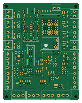
About the PneuCNTRL2 PCB
PneuCNTRL2 is an open source NXP PCB design by hnnswldschtz, published on GitHub under the Custom license license. It is a 2-layer board measuring 84.5 × 107.5 mm, with 161 components from 34 distinct parts.
Its main chip is the Teensy3.2, from the NXP family. Other key parts include the LM358, LM317_TO-220, MCP4728 and ADS1115IDGS. By type, the board carries 74 connectors, 41 resistors, 9 capacitors, 8 transistors, 8 diodes and 7 ICs.
It belongs with the displays & leds designs in this gallery.
From the project
- custom PCB released as openhardware under cern-ohl-w v2 license - based on teensy3.2 - ads1115 for ADC - MCP4728 for DAC - 4x festo 571482 pressure sensors - 4x smc 5/3 electric valves - 4x Festo proportional piezo valves (VEAB-L-26-D7-Q4-V1-1R1) - LCD i2c display
- custom PCB released as openhardware under cern-ohl-w v2 license - based on teensy3.2 - ads1115 for ADC - MCP4728 for DAC - 4x festo 571482 pressure sensors - 4x smc 5/3 electric valves - 4x Festo proportional piezo valves (VEAB-L-26-D7-Q4-V1-1R1) - LCD i2c display
libraries used: ADS1115lite: https://github.com/terryjmyers/ADS1115-Lite AdafruitMCP4728: https://github.com/adafruit/AdafruitMCP4728 AdafruitNeoPixel: https://github.com/adafruit/AdafruitNeoPixel LiquidCrystalI2C: https://github.com/johnrickman/LiquidCrystalI2C -> this gives a massive delay when used! maybe avoid!!…

Main components on the PneuCNTRL2
PneuCNTRL2 bill of materials (BOM)
161 components, 34 distinct parts.
| Qty | Part | Footprint | Refs |
|---|---|---|---|
| 2 | LM358 | SOIC-8_3.9x4.9mm_P1.27mm | U1, U2 |
| 1 | LM317_TO-220 | SOIC-8_3.9x4.9mm_P1.27mm | U3 |
| 1 | Teensy3.2 | Teensy30_31_32_All_Pins | U4 |
| 1 | MCP4728 | MSOP-10_3x3mm_P0.5mm | U5 |
| 2 | ADS1115IDGS | TSSOP-10_3x3mm_P0.5mm | U6, U7 |
| 8 | BSS138 | SOT-23 | Q1, Q2, Q3, Q4, Q5, Q6, Q7, Q8 |
| 8 | Screw_term. | TerminalBlock_Phoenix_MKDS-1,5-2_1x02_P5.00mm_Horizontal | J1, J2, J3, J4, J5, J6, J7, J8 |
| 4 | Screw_Terminal_01x04 | TerminalBlock_Phoenix_MKDS-1,5-4_1x04_P5.00mm_Horizontal | J9, J10, J11, J12 |
| 4 | Screw_Terminal_01x04 | TerminalBlock_Phoenix_MKDS-1,5-3_1x03_P5.00mm_Horizontal | J13, J14, J15, J16 |
| 1 | POWER TERMINAL | TerminalBlock_Phoenix_MKDS-1,5-2_1x02_P5.00mm_Horizontal | J17 |
| 1 | Conn_02x06_Odd_Even | IDC-Header_2x06_P2.54mm_Vertical | J18 |
| 1 | Conn_02x05_Odd_Even | IDC-Header_2x05_P2.54mm_Vertical | J19 |
| 1 | Conn_02x06_Odd_Even | IDC-Header_2x03_P2.54mm_Vertical | J20 |
| 54 | solderPin | Pin_D1.0mm_L10.0mm | p1, p2, p3, p4, p5, p6, p7, p8 +46 |
| 4 | jumper | SolderJumper-3_P1.3mm_Bridged12_Pad1.0x1.5mm | JP1, JP2, JP3, JP4 |
| 1 | SolderJumper_2_Bridged | SolderJumper-2_P1.3mm_Bridged2Bar_Pad1.0x1.5mm | JP5 |
| 1 | +3V | Pin_D1.0mm_L10.0mm | TP1 |
| 1 | +10V | Pin_D1.0mm_L10.0mm | TP5 |
| 1 | +24V | Pin_D1.0mm_L10.0mm | TP6 |
| 1 | GND | Pin_D1.0mm_L10.0mm | TP7 |
Show 14 more
| Qty | Part | Footprint | Refs |
|---|---|---|---|
| 1 | lm2596_dcdc | LM2596 DC-DC | dcdc1 |
| 8 | 1N4001 | D_SMA | D1, D2, D3, D4, D5, D6, D7, D8 |
| 4 | FerriteBead | C_0805_2012Metric_Pad1.18x1.45mm_HandSolder | FB1, FB2, FB3, FB4 |
| 1 | 100n 35V | C_1206_3216Metric | C1 |
| 1 | 10uF | C_1206_3216Metric | C2 |
| 1 | 1µ 35V | C_1206_3216Metric | C3 |
| 1 | 0,1uF | C_1206_3216Metric | C4 |
| 2 | 1uF | C_1206_3216Metric | C5, C6 |
| 3 | ? | C_1206_3216Metric | C7, C8, C9 |
| 24 | 1k | R_0805_2012Metric_Pad1.20x1.40mm_HandSolder | R1, R2, R3, R4, R5, R6, R7, R8 +16 |
| 1 | 270 | R_0805_2012Metric_Pad1.20x1.40mm_HandSolder | R9 |
| 1 | 2k | R_0805_2012Metric_Pad1.20x1.40mm_HandSolder | R10 |
| 3 | 4k7 | R_0805_2012Metric_Pad1.20x1.40mm_HandSolder | R27, R28, R29 |
| 12 | 10k | R_0805_2012Metric_Pad1.20x1.40mm_HandSolder | R30, R31, R32, R33, R34, R35, R36, R37 +4 |
PneuCNTRL2 design files
The KiCad project lives in the hnnswldschtz/pneuCNTRL2 repository on GitHub; these links point at the commit this page was built from.
PneuCNTRL2: common questions
What microcontroller does the PneuCNTRL2 use?
The PneuCNTRL2 is built around the Teensy3.2, from the NXP family.
How big is the PneuCNTRL2 PCB?
The PneuCNTRL2 measures 84.5 × 107.5 mm, has 2 copper layers and is 1.6 mm thick.
How many components are on the PneuCNTRL2?
161 components, from 34 distinct parts. The full bill of materials is listed on this page.
Where can I download the PneuCNTRL2 design files?
From the hnnswldschtz/pneuCNTRL2 repository on GitHub, which has the KiCad layout and the schematic; the links under Design files point to each one.
Can I use the PneuCNTRL2 design in my own project?
It is published under Custom license, which limits how it may be reused; read the license before building on it.
Can I test firmware for the PneuCNTRL2 without the hardware?
Yes. HardLabs builds a simulation of the board from its netlist and BOM, so you can run and debug NXP firmware against it before you order a PCB.
Similar boards
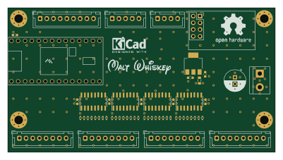 NXP
32Bit shift register
MaltWhiskey
100 × 54 mm56 parts4LNo license763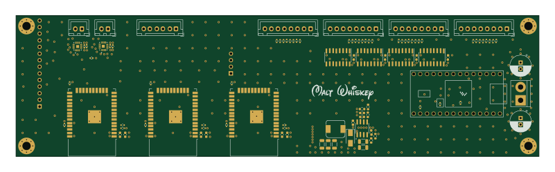 NXP
Mega-Cube-Board
200 × 54 mm100 parts4LNo license763 NXP
MCL6809
MicroCoreLabs
32.3 × 61 mm7 parts4LNo license532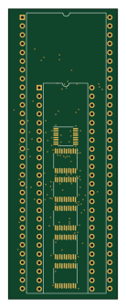 NXP
MCL68
31.6 × 84.1 mm13 parts4LNo license532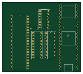 NXP
MCL65+
72.6 × 64.1 mm6 parts2LNo license532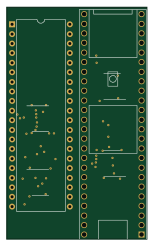 NXP
MCLZ8
37.1 × 61.5 mm6 parts4LNo license532