Ethernet to spi

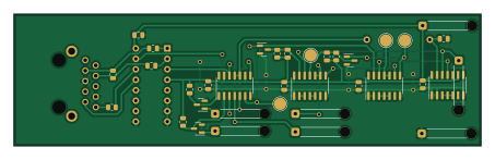
About the Ethernet to spi PCB
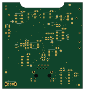
Ethernet to spi is an open source PCB design by imihajlow, published on GitHub under the GPL-3.0 license. It is a 2-layer board measuring 113 × 32 mm, with 34 components from 24 distinct parts.
Other key parts include the 74HC86, 74HC14, 75C1168, 74HC08 and 74HC32. By type, the board carries 10 capacitors, 8 connectors, 7 resistors, 5 ICs and 4 transistors.
From the project
An Ethernet to SPI converter using 7400-series ICs
The Nucleo64 shield schematic files are located in sch/shield/.
The firmware for stm32f401 is located in stm32eth-f401/.
The idea is to convert the Manchester-encoded 10BASE-T signal to SPI and use an STM32 MCU to parse it.
A 75C1168 chip is used to convert differential signals to 5V logic levels.
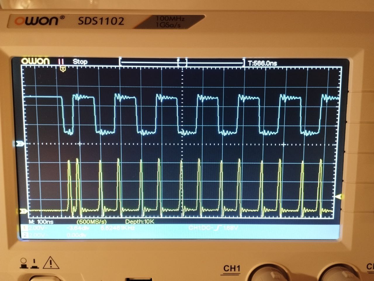
Then, edges are detected using a 74HC86 XOR.
Blue is the input signal, yellow - detected edges.
Main components on the Ethernet to spi
Ethernet to spi bill of materials (BOM)
34 components, 24 distinct parts.
| Qty | Part | Footprint | Refs |
|---|---|---|---|
| 1 | 74HC86 | SOIC-14_3.9x8.7mm_P1.27mm | U1 |
| 1 | 74HC14 | SOIC-14_3.9x8.7mm_P1.27mm | U2 |
| 1 | 75C1168 | DIP-16_W7.62mm | U3 |
| 1 | 74HC08 | SOIC-14_3.9x8.7mm_P1.27mm | U4 |
| 1 | 74HC32 | SOIC-14_3.9x8.7mm_P1.27mm | U5 |
| 4 | 2N7002 | SOT-23 | Q1, Q2, Q3, Q4 |
| 1 | G8X-188S7-BP | G8X-188S7-BP | J1 |
| 1 | mosi | SolderWire-0.25sqmm_1x01_D0.65mm_OD2mm_Relief | J2 |
| 1 | sck_tx | SolderWire-0.25sqmm_1x01_D0.65mm_OD2mm_Relief | J3 |
| 1 | mosi_tx | SolderWire-0.25sqmm_1x01_D0.65mm_OD2mm_Relief | J4 |
| 1 | cs | SolderWire-0.25sqmm_1x01_D0.65mm_OD2mm_Relief | J5 |
| 1 | sck | SolderWire-0.25sqmm_1x01_D0.65mm_OD2mm_Relief | J6 |
| 1 | vcc | SolderWire-0.25sqmm_1x01_D0.65mm_OD2mm_Relief | J7 |
| 1 | gnd | SolderWire-0.25sqmm_1x01_D0.65mm_OD2mm_Relief | J8 |
| 7 | 0.1 | C_0805_2012Metric | C1, C2, C3, C4, C5, C6, C7 |
| 1 | 200p | C_0805_2012Metric | C8 |
| 1 | 0 | C_0805_2012Metric | C9 |
| 1 | 10p | C_0805_2012Metric | C10 |
| 1 | 100 | R_0805_2012Metric | R1 |
| 1 | 470 | R_0805_2012Metric | R2 |
Show 4 more
| Qty | Part | Footprint | Refs |
|---|---|---|---|
| 1 | 2k | R_0805_2012Metric | R3 |
| 1 | 500 | R_0805_2012Metric | R4 |
| 1 | 1k | R_Axial_DIN0207_L6.3mm_D2.5mm_P15.24mm_Horizontal | R5 |
| 2 | 1k | R_0805_2012Metric | R6, R7 |
Ethernet to spi design files
The KiCad project lives in the imihajlow/ethernet-to-spi repository on GitHub; these links point at the commit this page was built from.
Ethernet to spi: common questions
How big is the Ethernet to spi PCB?
The Ethernet to spi measures 113 × 32 mm, has 2 copper layers and is 1.6 mm thick.
How many components are on the Ethernet to spi?
34 components, from 24 distinct parts. The full bill of materials is listed on this page.
Where can I download the Ethernet to spi design files?
From the imihajlow/ethernet-to-spi repository on GitHub, which has the KiCad layout and the schematic; the links under Design files point to each one.
Can I use the Ethernet to spi design in my own project?
Yes, under the terms of its GPL-3.0 license, which imihajlow chose for the repository.