
Telematics tracker

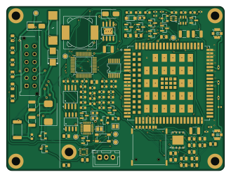
About the Telematics tracker PCB
Telematics tracker is an open source PCB design by Immanueldavidckp, published on GitHub. It is a 4-layer board measuring 82 × 62 mm, with 190 components from 77 distinct parts.
Other key parts include the EC200UCNAA-N05-SGNSA, AT32F403ACGT7, QMI8658B, SIT1051AT/3 and EG11752. By type, the board carries 74 resistors, 61 capacitors, 16 diodes, 14 transistors, 9 ICs and 5 inductors.
It belongs with the rf & radio and power & battery designs in this gallery.
From the project
CAN-connected GPS/LTE tracker for rental MEWPs (boom/scissor lifts). Powered from machine batteries with internal Li-ion backup, 2 isolated digital inputs, 2 low-side outputs, ignition sense, 6-axis IMU, and ≥6 days of local telemetry buffering.
CAN-connected GPS/LTE tracker for rental MEWPs (boom/scissor lifts). Powered from machine batteries with internal Li-ion backup, 2 isolated digital inputs, 2 low-side outputs, ignition sense, 6-axis IMU, and ≥6 days of local telemetry buffering.
Status: milestone 3 complete. Schematics are drawn and ERC-clean. Layout has not started and is gated on the open flags below.
Main components on the Telematics tracker
Telematics tracker bill of materials (BOM)
190 components, 77 distinct parts.
| Qty | Part | Footprint | Refs |
|---|---|---|---|
| 1 | EC200UCNAA-N05-SGNSA | LCC-LGA-144_L31.0-W28.0-P1.30_L610-CN-02 | U1 |
| 1 | AT32F403ACGT7 | LQFP-48_L7.0-W7.0-P0.50-LS9.0-BL_1 | U2 |
| 1 | QMI8658B | LGA-14_L3.0-W2.5-P0.50-TL | U3 |
| 1 | SIT1051AT/3 | SOP-8_L4.9-W3.9-P1.27-LS6.0-BL | U4 |
| 1 | EG11752 | SOIC-8_L4.9-W3.9-P1.27-LS6.0-BL-EP3.3-1 | U5 |
| 1 | BQ25606RGER | VQFN-24_L4.0-W4.0-P0.50-TL-EP2.8 | U6 |
| 1 | GD25Q64ESIGR | SOP-8_L5.3-W5.3-P1.27-LS8.0-BL | U7 |
| 1 | TXB0104PWR | TSSOP-14_L5.0-W4.4-P0.65-LS6.4-BL | U8 |
| 1 | ME6211C33M5G | SOT-23-5_L3.0-W1.7-P0.95-LS2.8-BL | U9 |
| 2 | AM2390N-TP | SOT-23-3_L2.9-W1.3-P1.90-LS2.4-BR | Q1, Q2 |
| 1 | AO3401A | SOT-23-3_L2.9-W1.3-P1.90-LS2.4-BR | Q3 |
| 10 | MMBT3904 | SOT-23 | Q4, Q5, Q6, Q7, Q8, Q9, Q10, Q11 +2 |
| 1 | MMBT3906 | SOT-23 | Q13 |
| 1 | NANO-SIM | SIM-SMD_YKSIM-PUSH137-140NANO | X1 |
| 1 | MFF2-eSIM-pads | eSIM_MFF2_VFDFPN8 | X2 |
| 1 | 8MHz | Crystal_SMD_3225-4Pin_3.2x2.5mm | Y1 |
| 1 | 32.768kHz | Crystal_SMD_3215-2Pin_3.2x1.5mm | Y2 |
| 1 | WAFER-MX3.0-12PZZ | XUNPU_MX3.0-12PZZ_2x06_P3.00mm_Vertical | J1 |
| 1 | B3B-XH-A | JST_XH_B3B-XH-A_1x03_P2.50mm_Vertical | J2 |
| 2 | U.FL | CONN-SMD_XY-IPEX1 | AF1, AF2 |
Show 57 more
| Qty | Part | Footprint | Refs |
|---|---|---|---|
| 1 | 1A 250V | FUSE-SMD_L10.1-W3.1 | F1 |
| 2 | EL357N(D) | OPTO-SMD-4_L4.4-W4.1-P2.54-LS7.0-BL | OK1, OK2 |
| 1 | S3M | SMB_L4.3-W3.6-LS5.3-RD | D1 |
| 1 | SMDJ100A | D_SMC | D2 |
| 1 | PESD1CAN | SOT-23_L2.9-W1.3-P1.90-LS2.4-BR | D3 |
| 4 | BAV99 | SOT-23 | D5, D6, D10, D11 |
| 3 | SS3200 | D_SMA | D7, D8, D16 |
| 1 | SMF5.0A | SOD-123FL_L2.7-W1.8-LS3.8-RD | D12 |
| 1 | NET | LED_0603_1608Metric | D13 |
| 1 | SMF05C | SOT-363_L2.0-W1.3-P0.65-LS2.1-BR | D14 |
| 1 | USBLC6-2SC6 | SOT-23-6_L2.9-W1.6-P0.95-LS2.8-BL | D15 |
| 1 | GRN | LED_0603_1608Metric | D20 |
| 1 | BLU | LED_0603_1608Metric | D21 |
| 1 | 600R@100MHz | L_0805_2012Metric | FB1 |
| 1 | 150uH 2.7A | IND-SMD_L12.3-W12.3 | L1 |
| 1 | ACT45B-510-2P | IND-SMD_4P-L4.5-W3.2-TL | L2 |
| 1 | 2.2uH | L1008 | L3 |
| 1 | 68nH | L_0402_1005Metric | L4 |
| 2 | 18pF | C_0603_1608Metric | C1, C2 |
| 2 | 6.8pF | C_0603_1608Metric | C3, C4 |
| 21 | 100nF | C_0603_1608Metric | C5, C6, C8, C9, C10, C11, C13, C20 +13 |
| 8 | 1uF | C_0603_1608Metric | C7, C14, C21, C42, C44, C61, C68, C69 |
| 2 | 4.7uF | C_0805_2012Metric | C12, C63 |
| 1 | 4.7nF | C_0603_1608Metric | C22 |
| 4 | 47uF X7R | C_1210_3225Metric | C40, C41, C81, C82 |
| 4 | DNP | C_0402_1005Metric | C48, C49, C50, C51 |
| 7 | 10uF | C_0805_2012Metric | C62, C65, C66, C67, C77, C78, C79 |
| 1 | 47nF | C_0603_1608Metric | C64 |
| 4 | 2.2uF 100V | C_1210_3225Metric | C70, C71, C73, C74 |
| 1 | 1uF 25V | C_0603_1608Metric | C75 |
| 1 | 100nF 25V | C_0603_1608Metric | C76 |
| 1 | 100nF | C_0402_1005Metric | C83 |
| 1 | 100pF C0G | C_0402_1005Metric | C84 |
| 1 | 10nF | C_0402_1005Metric | C85 |
| 11 | 10k | R_0805_2012Metric | R1, R2, R25, R26, R43, R44, R47, R48 +3 |
| 3 | 0R | R_0805_2012Metric | R3, R69, R70 |
| 3 | 1k | R_0805_2012Metric | R4, R6, R65 |
| 8 | 4.7k | R_0805_2012Metric | R5, R42, R46, R53, R55, R57, R59, R64 |
| 4 | 2.2k | R_0805_2012Metric | R7, R8, R45, R49 |
| 2 | 60.4R | R_0805_2012Metric | R11, R12 |
| 6 | 12k | R_1206_3216Metric | R14, R15, R16, R17, R18, R19 |
| 9 | 47k | R_0805_2012Metric | R21, R22, R52, R54, R56, R58, R60, R61 +1 |
| 2 | 100R | R_0805_2012Metric | R23, R24 |
| 8 | 100k | R_0805_2012Metric | R30, R31, R32, R33, R34, R35, R50, R81 |
| 2 | 9.1k | R_0805_2012Metric | R36, R37 |
| 2 | 1M | R_0805_2012Metric | R38, R39 |
| 3 | 33R | R_0805_2012Metric | R66, R67, R68 |
| 2 | 0R | R_0402_1005Metric | R71, R72 |
| 1 | 1R 2512 anti-surge | R_2512_6332Metric | R80 |
| 1 | 0R (F-12) | R_0805_2012Metric | R82 |
| 1 | 4.3k | R_0805_2012Metric | R83 |
| 1 | 1.5k | R_0805_2012Metric | R84 |
| 1 | 976R | R_0805_2012Metric | R85 |
| 1 | 536R | R_0805_2012Metric | R86 |
| 1 | 5.23k | R_0805_2012Metric | R88 |
| 1 | 30.1k | R_0805_2012Metric | R89 |
| 1 | 68R | R_1210_3225Metric | R90 |
Telematics tracker design files
The KiCad project lives in the Immanueldavidckp/schematics repository on GitHub; these links point at the commit this page was built from.
- Layouttelematics-tracker.kicad_pcb
- Schematictelematics-tracker.kicad_sch
Telematics tracker: common questions
How big is the Telematics tracker PCB?
The Telematics tracker measures 82 × 62 mm, has 4 copper layers and is 1.6 mm thick.
How many components are on the Telematics tracker?
190 components, from 77 distinct parts. The full bill of materials is listed on this page.
Where can I download the Telematics tracker design files?
From the Immanueldavidckp/schematics repository on GitHub, which has the KiCad layout and the schematic; the links under Design files point to each one.
Can I use the Telematics tracker design in my own project?
The repository has no license, so all rights stay with Immanueldavidckp. Use it as a reference, and ask the author before reusing the design.
Similar boards

EinkPDA screen
TalismanDesign
95 × 54 mm27 parts2LApache-2.02.0k
Stack chan
stack-chan
50 × 50 mm33 parts2LApache-2.01.7k
Display Carrier
AxxAxx
35.6 × 58.2 mm5 parts2LGPL-3.01.7k
ProgrammingAdapter
stuartpittaway
10.5 × 83 mm3 parts2LCC-BY-NC-4.01.1k
TemperaturePCB PANEL
116 × 75.5 mm178 parts2LCC-BY-NC-4.01.1k
Module 16S PassiveBalanceAddOn
61 × 74 mm86 parts2LCC-BY-NC-4.01.1k