
Main Board

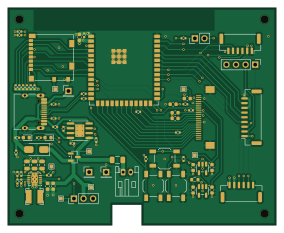
About the Main Board
Main Board is an open source ESP32 PCB design by jackshisd, published on GitHub. It is a 4-layer board measuring 71 × 57.5 mm, with 74 components from 40 distinct parts.
Its main chip is the ESP32-S3-WROOM-2, from the ESP32 family. Other key parts include the TPS63060, TP4056-42-ESOP8, TLV75528PDBV and AP2112K-1.2. By type, the board carries 25 resistors, 21 capacitors, 6 connectors, 5 ICs, 4 diodes and 1 transistor.
It belongs with the audio, iot & wireless and wearables designs in this gallery.
From the project
ESP32-based infant wearable for audio and video data acquisition with SD storage, BLE-triggered recording, and USB mass storage support.
WARNING: This project writes audio/video files to the SD card. Back up your data before testing.
Records: - Audio: WAV via I2S mic (ICS-43434), mic0001.wav, mic0002.wav, ... - Contact audio: WAV via ES8388 contact mic board, CT0001.WAV, CT0002.WAV, ... - Video: MJPEG via OV2640, VID0001.MJP, VID0002.MJP, ...
Core features: - SDMMC FAT mount/unmount - USB MSC to expose the SD card when idle - SSD1306 I2C OLED status - Button UI - BLE scan trigger (advertisements) with timestamped filenames - Simultaneous standard mic + contact mic recording to separate WAV files - Boot-time ES8388 codec…
Main components on the Main Board
Main Board bill of materials (BOM)
74 components, 40 distinct parts — part numbers from the project's BOM.
| Qty | Part | Footprint | Refs |
|---|---|---|---|
| 1 | ESP32-S3-WROOM-2 | ESP32-S3-WROOM-2 | U1 |
| 1 | TPS63060 | Texas_S-PWSON-N10_ThermalVias | U2 |
| 1 | TP4056-42-ESOP8 | SOIC-8-1EP_3.9x4.9mm_P1.27mm_EP2.41x3.3mm_ThermalVias | U3 |
| 1 | TLV75528PDBV | SOT-23-5 | U4 |
| 1 | AP2112K-1.2 | SOT-23-5 | U6 |
| 1 | AO3401A | SOT-23 | Q1 |
| 1 | MICRO_SD_CARD_DET1 Micro_SD_Card_Det1 | microSD_HC_Molex_104031-0811 | J1 |
| 1 | CONN_01X09_SOCKET Conn_01x09_Socket | JST_GH_SM09B-GHS-TB_1x09-1MP_P1.25mm_Horizontal | J3 |
| 1 | MIC 1 Connector | JST_GH_SM06B-GHS-TB_1x06-1MP_P1.25mm_Horizontal | J4 |
| 1 | MIC 2 Connector | JST_GH_SM06B-GHS-TB_1x06-1MP_P1.25mm_Horizontal | J5 |
| 1 | USB_C_RECEPTACLE_USB2.0_16P USB_C_Receptacle_USB2.0_16P | USB_C_Receptacle_HRO_TYPE-C-31-M-12 | J6 |
| 1 | OLED | PinHeader_1x04_P2.54mm_Vertical | J7 |
| 2 | TestPoint | PinHeader_1x01_P2.54mm_Vertical | 3V3, GND1 |
| 1 | FerriteBead | R_0603_1608Metric | 600Ω@100MHz1 |
| 3 | SW_Push | SW_SPST_TL3342 | BOOT1, RESET1, USER_INPUT1 |
| 1 | Battery_Cell | JST_PH_S2B-PH-K_1x02_P2.00mm_Horizontal | BT1 |
| 1 | OV2640 | OV2640 | CAM1 |
| 1 | Fuse | Fuse_1206_3216Metric | F1 |
| 1 | SW_SPST | PinHeader_1x03_P2.54mm_Vertical | SW1 |
| 1 | TestPoint | PinHeader_1x01_P2.54mm_Vertical | TP3 |
Show 20 more
| Qty | Part | Footprint | Refs |
|---|---|---|---|
| 1 | LED | PinHeader_1x02_P2.54mm_Vertical | D1 |
| 2 | LED | LED_0603_1608Metric | D2, D3 |
| 1 | SS14 | D_SMA | D5 |
| 1 | 1UH 1uH | L_Bourns-SRN4018 | L1 |
| 3 | 0.1UF 0.1uF | C_0402_1005Metric | C1, C3, C8 |
| 3 | 10UF 10uF | C_0402_1005Metric | C2, C7, C10 |
| 3 | 10UF 10uF | C_0603_1608Metric | C4, C5, C6 |
| 1 | 10PF 10pF | C_0402_1005Metric | C9 |
| 3 | 22UF 22uF | C_0805_2012Metric | C11, C12, C13 |
| 4 | 0.1UF 0.1uF | C_0603_1608Metric | C14, C15, C16, C17 |
| 4 | 1UF 1uF | C_0603_1608Metric | C18, C19, C20, C21 |
| 4 | 10K 10k | R_0402_1005Metric | R1, R12, R13, R14 |
| 6 | 47K 47k | R_0402_1005Metric | R2, R3, R4, R5, R6, R7 |
| 4 | 22 | R_0402_1005Metric | R9, R10, R23, R28 |
| 3 | 4.7K | R_0402_1005Metric | R11, R17, R26 |
| 2 | 0 | R_0402_1005Metric | R15, R27 |
| 1 | 560K 560k | R_0402_1005Metric | R16 |
| 2 | 100K 100k | R_0402_1005Metric | R18, R24 |
| 1 | 1M | R_0402_1005Metric | R19 |
| 2 | 5.1K 5.1k | R_0402_1005Metric | R21, R22 |
Main Board design files
The KiCad project lives in the jackshisd/EoC-Lab repository on GitHub; these links point at the commit this page was built from.
Main Board: common questions
What microcontroller does the Main Board use?
The Main Board is built around the ESP32-S3-WROOM-2, from the ESP32 family.
How big is the Main Board?
The Main Board measures 71 × 57.5 mm, has 4 copper layers and is 1.6 mm thick.
How many components are on the Main Board?
74 components, from 40 distinct parts, with part numbers taken from the project's own BOM. The full bill of materials is listed on this page.
Where can I download the Main Board design files?
From the jackshisd/EoC-Lab repository on GitHub, which has the KiCad layout, the schematic and the BOM; the links under Design files point to each one.
Can I use the Main Board design in my own project?
The repository has no license, so all rights stay with jackshisd. Use it as a reference, and ask the author before reusing the design.
Can I test firmware for the Main Board without the hardware?
Yes. HardLabs builds a simulation of the board from its netlist and BOM, so you can run and debug ESP32 firmware against it before you order a PCB.
More boards in EoC-Lab

Similar boards
 ESP32
Open Book Abridged Edition
joeycastillo
85 × 115 mm65 parts2LCC-BY-SA-4.08.1k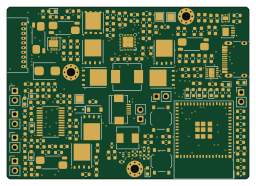 ESP32
Powertrain
byrantech
64 × 45.4 mm171 parts4LMIT4.3k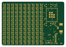 ESP32
Badge
atopile
56.3 × 39 mm239 parts4LMIT4.0k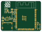 ESP32
Esp32 minimal
36.2 × 26.8 mm20 parts2LMIT4.0k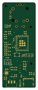 ESP32
Controller
StuckAtPrototype
29 × 74 mm58 parts4LApache-2.03.8k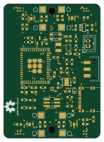 ESP32
Racer
36 × 50.2 mm70 parts4LApache-2.03.8k