
23 open source boards using the TPS63060
Real designs built with the TPS63060, from public GitHub projects: a quick way to see how others power, decouple and connect it. Each board comes with its KiCad files, full parts list and a render — and you can simulate its firmware on HardLabs.
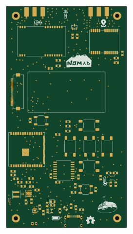 ESP32
Nomad
0Zane
65 × 120 mm69 parts2LMIT15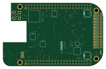
RoboCape
PREDICT-EPFL
86.4 × 54.6 mm113 partsNo license4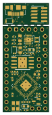 RP2040/RP2350
RP2350-ProMini
red-scorp
17.8 × 41.9 mm46 parts4LNo license4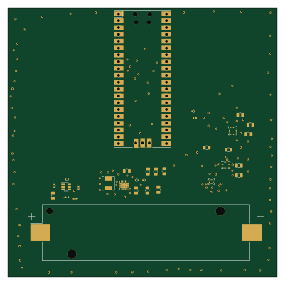 RP2040/RP2350
BuhSat v0
Sadteeto
100 × 100 mm32 parts2LMIT4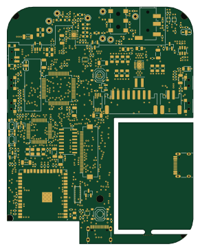 ESP32
Hactar PCB - Finn Berg & Brett Regnier
Quicr
71.5 × 91 mm203 parts4LBSD-2-Clause3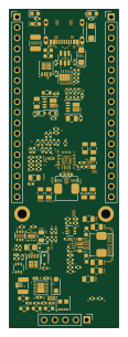
Kicad usb pd power manager
flisboac
26.2 × 76.2 mm141 parts4LCERN-OHL-P-2.03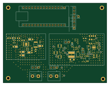 AVR/Arduino
MPPT
aati106
90.4 × 69.6 mm93 parts2LNo license2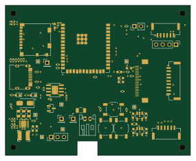 ESP32
Main Board
jackshisd
71 × 57.5 mm74 parts4LNo license2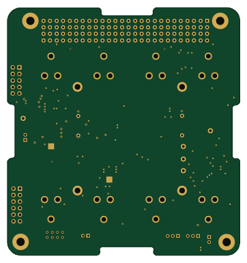 STM32
Battery board v2
queens-satellite-team
90.2 × 96 mm119 parts4LNo license1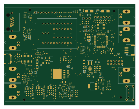 STM32
Clock
fluffy
119 × 92 mm192 parts2LBSD-3-Clause0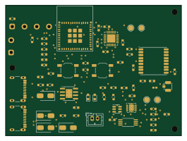 ESP32
ScholDigi
Sheep26
66 × 49 mm65 parts2LNo license0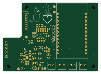
ESP32-Clock-Gallery
nickzswammer
86.8 × 63 mm43 parts2LNo license0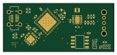 RP2040/RP2350
Thermometer CD Project
Wik19
42.5 × 18.5 mm39 parts2LNo license0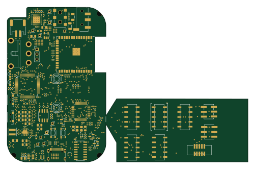 ESP32
Hactar PCB - Finn Berg, Brett Regnier
125 × 80 mm173 parts4LBSD-2-Clause3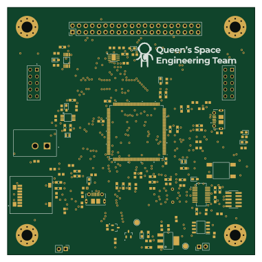 STM32
STM32 Breakout
95 × 95 mm108 parts4LNo license1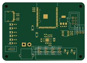 ESP32
Typhoon Motherboard
hpvdt
73.5 × 52.8 mm51 parts2LNo license1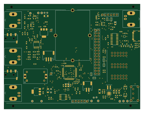 STM32
Blink
119 × 92 mm131 parts2LBSD-3-Clause0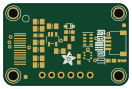
Adafruit OLED 128x32 Mono I2C STEMMA QT rev B
33 × 21.6 mm24 parts2LNo license2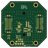
Skycan eps
skycan
50 × 50 mm36 parts2LCustom license0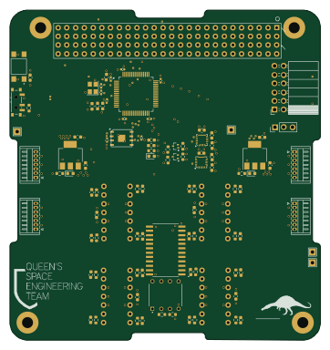 STM32
MC SunSensor
90.2 × 95.9 mm104 parts4LNo license1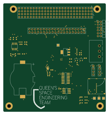 STM32
Pc104-template
90.2 × 95.9 mm47 parts4LNo license1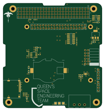 STM32
Obc db
90.2 × 95.9 mm44 parts4LNo license1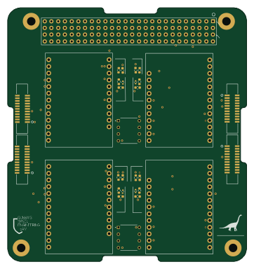 STM32
ReactionWheel
90.2 × 95.9 mm31 parts4LNo license1
How designs wire the TPS63060
Read from the KiCad layouts of 15 open source designs, one per repository: what each pin of the TPS63060 connects to, and the resistors, capacitors and other passives placed on it.
- The L1 pin has a inductor on 13 of 15 designs, most often 1 µH (then 1.5 µH).
- The L2 pin has a inductor on 13 of 14 designs, most often 1 µH (then 1.5 µH).
- The VAUX pin has a capacitor to GND on 12 of 14 designs, most often 100 nF.
- The FB pin has a resistor to GND on 12 of 14 designs, most often 100 kΩ (then 111 kΩ).
| Pin | Connected to | Parts on the pin |
|---|---|---|
| L1pin 1 | Connected to: Signal 93% |
|
| VINpin 2 | Connected to: Signal 48% · GND 24% · VIN 29% |
|
| ENpin 3 | Connected to: Signal 56% · VIN 33% |
|
| PS/SYNCpin 4 | Connected to: GND 73% · a signal 20% | — |
| PGpin 5 | Connected to: Signal 87% |
|
| VAUXpin 6 | Connected to: Signal 100% |
|
| GNDpin 7 | Connected to: GND 86% | — |
| FBpin 8 | Connected to: Signal 100% |
|
| VOUTpin 9 | Connected to: 3.3V 71% · a signal 29% |
|
| L2pin 10 | Connected to: Signal 93% |
|
| PGNDpin 11 | Connected to: GND 89% | — |
Connections count pins, parts count designs; values in brackets are how many parts had that value. Designs read include Nomad by 0Zane, RoboCape by PREDICT-EPFL, RP2350-ProMini by red-scorp and BuhSat v0 by Sadteeto.
The TPS63060 in open source designs
The gallery holds 23 open source boards using the TPS63060 from 15 GitHub repositories; a typical one measures about 86.8 × 80 mm and carries around 69 components.
50% are two-layer designs, the rest use four layers or more, and 30% carry an open source license.
The most starred is Nomad by 0Zane.
Parts used alongside the TPS63060
Microcontrollers on boards using the TPS63060
What boards using the TPS63060 are built for
TPS63060: common questions
Where can I find a TPS63060 reference design?
Each of the 23 boards on this page is a real design using the TPS63060. Open one to see how it is wired up, with the full BOM, a render of the layout and links to its KiCad files.
How is the TPS63060 L1 pin connected?
The L1 pin has a inductor on 13 of 15 designs, most often 1 µH (then 1.5 µH). Counted from the KiCad layouts of 15 open source designs using the TPS63060.
How is the TPS63060 L2 pin connected?
The L2 pin has a inductor on 13 of 14 designs, most often 1 µH (then 1.5 µH). Counted from the KiCad layouts of 15 open source designs using the TPS63060.
How is the TPS63060 VAUX pin connected?
The VAUX pin has a capacitor to GND on 12 of 14 designs, most often 100 nF. Counted from the KiCad layouts of 15 open source designs using the TPS63060.
What parts are used alongside the TPS63060?
The ESP32-S3-WROOM-1, CH340C, MAX17048G_T10, STM32F405RGTx and TP4056-42-ESOP8 appear in the most repositories here.
Which microcontrollers do boards using the TPS63060 use?
Most are built on STM32 (8), ESP32 (6), RP2040/RP2350 (3) and AVR/Arduino (1).
How big is a typical board using the TPS63060?
The median is 86.8 × 80 mm, and 50% are two-layer designs.
What is the most popular open source board using the TPS63060?
By GitHub stars, Nomad by 0Zane, with 15 stars.
Can I simulate one of these boards using the TPS63060 before building it?
Yes. HardLabs turns a board's netlist and BOM into a working simulation, so you can boot and test firmware against it with no hardware on your desk.