
PCB Drivers + Sensores

About the PCB Drivers + Sensores
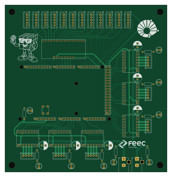
PCB Drivers + Sensores is an open source PCB design by JagdtigerAusfb, published on GitHub. It is a 2-layer board measuring 150 × 155 mm, with 59 components from 16 distinct parts.
Other key parts include the BOB-09056 and Pololu_Breakout_A4988. By type, the board carries 9 diodes, 9 resistors, 7 connectors, 6 modules, 6 capacitors and 1 IC.
It belongs with the robotics & motion, sensors and dev boards & breakouts designs in this gallery.
From the project
Tudo do Raiden
This board functions as a custom shield for the Arduino Mega. It integrates everything needed to control the mechanics and inputs of the project: 6x A4988 Stepper Motor Drivers 12x Color Sensor Connectors 1x Multiplexer** (to handle the sensor inputs)
The system is powered by a 12V power supply with two output ports. We strongly advise using both ports. During testing, relying on a single port caused voltage drops, which resulted in some motors stalling.
Main components on the PCB Drivers + Sensores
PCB Drivers + Sensores bill of materials (BOM)
59 components, 16 distinct parts.
| Qty | Part | Footprint | Refs |
|---|---|---|---|
| 1 | BOB-09056 | MODULE_BOB-09056 | U1 |
| 6 | Pololu_Breakout_A4988 | Pololu_Breakout-16_15.2x20.3mm | A1, A2, A3, A4, A5, A6 |
| 1 | Power | PinSocket_1x08_P2.54mm_Vertical | J1 |
| 1 | PWM | PinSocket_1x10_P2.54mm_Vertical | J2 |
| 2 | Analog | PinSocket_1x08_P2.54mm_Vertical | J3, J5 |
| 1 | PWM | PinSocket_1x08_P2.54mm_Vertical | J4 |
| 1 | Communication | PinSocket_1x08_P2.54mm_Vertical | J6 |
| 1 | Digital | PinSocket_2x18_P2.54mm_Vertical | J7 |
| 2 | Barrel_Jack_Switch | BarrelJack_Horizontal | +12V_1, +12V_2 |
| 6 | Conn_01x04 | JST_XH_B4B-XH-A_1x04_P2.50mm_Vertical | Driver_Conn_1, Driver_Conn_2, Driver_Conn_3, Driver_Conn_4, Driver_Conn_5, Driver_Conn_6 |
| 1 | SW_Push | SW_PUSH_6mm | SW1 |
| 12 | Conn_01x05 | JST_XH_B5B-XH-A_1x05_P2.50mm_Vertical | Sensor_1, Sensor_2, Sensor_3, Sensor_4, Sensor_5, Sensor_6, Sensor_7, Sensor_8 +4 |
| 9 | LED | LED_D5.0mm | D1, D2, D3, D4, D5, D6, D7, D8 +1 |
| 6 | 100uF | CP_Radial_D8.0mm_P3.50mm | C1, C2, C3, C4, C5, C6 |
| 7 | 330 | R_Axial_DIN0207_L6.3mm_D2.5mm_P10.16mm_Horizontal | R1, R2, R3, R4, R5, R6, R7 |
| 2 | 1k | R_Axial_DIN0207_L6.3mm_D2.5mm_P10.16mm_Horizontal | R8, R9 |
PCB Drivers + Sensores design files
The KiCad project lives in the JagdtigerAusfb/Rubiks_Cube_Solving_Robot_EXTENCUBE_UNICAMP repository on GitHub; these links point at the commit this page was built from.
PCB Drivers + Sensores: common questions
How big is the PCB Drivers + Sensores?
The PCB Drivers + Sensores measures 150 × 155 mm, has 2 copper layers and is 1.6 mm thick.
How many components are on the PCB Drivers + Sensores?
59 components, from 16 distinct parts. The full bill of materials is listed on this page.
Where can I download the PCB Drivers + Sensores design files?
From the JagdtigerAusfb/Rubiks_Cube_Solving_Robot_EXTENCUBE_UNICAMP repository on GitHub, which has the KiCad layout and the schematic; the links under Design files point to each one.
Can I use the PCB Drivers + Sensores design in my own project?
The repository has no license, so all rights stay with JagdtigerAusfb. Use it as a reference, and ask the author before reusing the design.
More boards in Rubiks_Cube_Solving_Robot_EXTENCUBE_UNICAMP
Similar boards

Sensor smd
scottbez1
40 × 20 mm5 parts2LApache-2.04.2k
Sensors
StuckAtPrototype
15.2 × 9 mm14 parts4LApache-2.03.8k
Stack chan
stack-chan
50 × 50 mm33 parts2LApache-2.01.7k
Microphone
Mentra-Community
5.5 × 6.1 mm6 parts2LMIT1.2k
Eecv breakout
rusefi
140.8 × 53.7 mm9 parts4LGPL-3.01.2k
134pin 7-967288-1
139.7 × 73.7 mm38 parts2LGPL-3.01.2k