
Mission space

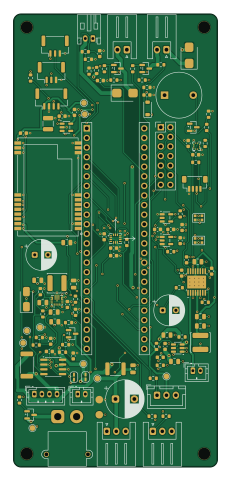
About the Mission space PCB
Mission space is an open source NXP PCB design by Jan-Philipp-Munsch, published on GitHub under the MIT license. It is a 4-layer board measuring 54 × 120 mm, with 118 components from 59 distinct parts.
Its main chip is the Teensy 4.1, from the NXP family. Other key parts include the TPS563201DDCR, TPS63070RNMR, AP2112K-3.3TRG1, ICM-42688-P and BMP390. By type, the board carries 40 capacitors, 36 resistors, 15 connectors, 10 ICs, 5 transistors and 4 diodes.
From the project
TVC model rocket (after BPS.space Scout F): Teensy 4.1 flight firmware, mainboard spec, project log
Stand 2026-10-21. Schaltplan und Platine von rev B werden hier aus Code erzeugt, nicht von Hand gezeichnet. Die Quelle der Wahrheit ist circuit.py: Schaltplan, Platine und Prüfungen werden daraus abgeleitet. Die Vorgabe ist die Spezifikation ../README.md (rev B). Dieses Dokument beschreibt, wie das Projekt entstanden ist, was fertig ist, was offen ist und wo bewusst von der Spezifikation abgewichen wurde. Die Fertigerwahl steht in ../Fertiger2026-10-21.md`.
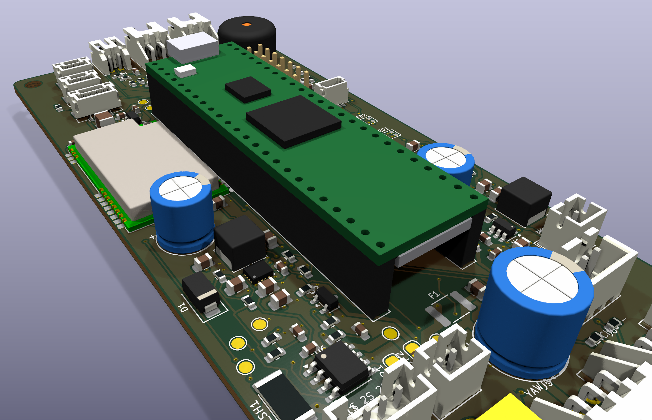
Main components on the Mission space
Mission space bill of materials (BOM)
118 components, 59 distinct parts.
| Qty | Part | Footprint | Refs |
|---|---|---|---|
| 1 | TPS563201DDCR | SOT-23-6 | U1 |
| 1 | TPS63070RNMR | VQFN-15_L3.0-W2.5-P0.50-BL | U2 |
| 1 | AP2112K-3.3TRG1 | SOT-23-5 | U3 |
| 1 | ICM-42688-P | LGA-14_L3.0-W2.5-P0.50-TL | U4 |
| 1 | BMP390 | LGA-10_L2.0-W2.0-P0.50-BL | U5 |
| 1 | INA219AIDR | SOIC-8_3.9x4.9mm_P1.27mm | U6 |
| 1 | DRV8833PWPR | HTSSOP-16-1EP_4.4x5mm_P0.65mm_EP3.4x5mm_Mask2.46x2.31mm_ThermalVias | U7 |
| 2 | 74AHCT1G125 | SOT-23-5 | U8, U9 |
| 1 | E22-400T22S | WIRELM-SMD_E22-400T22S_1 | U10 |
| 1 | Teensy 4.1 | Teensy41_Socket | A1 |
| 2 | AO3401A | SOT-23 | Q1, Q2 |
| 3 | AO3400A | SOT-23 | Q3, Q4, Q5 |
| 1 | XT30PW-M | AMASS_XT30PW-M_1x02_P2.50mm_Horizontal | J1 |
| 1 | J_BAT1 | JST_PH_B2B-PH-K_1x02_P2.00mm_Vertical | J2 |
| 1 | J_SW | JST_PH_B4B-PH-K_1x04_P2.00mm_Vertical | J3 |
| 1 | J_ARM | JST_PH_S2B-PH-K_1x02_P2.00mm_Horizontal | J4 |
| 1 | J_SERVO1 | JST_XH_S3B-XH-A_1x03_P2.50mm_Horizontal | J5 |
| 1 | J_SERVO2 | JST_XH_S3B-XH-A_1x03_P2.50mm_Horizontal | J6 |
| 1 | J_SERVO3 | JST_XH_B3B-XH-A_1x03_P2.50mm_Vertical | J7 |
| 1 | J_MOT | JST_PH_B2B-PH-K_1x02_P2.00mm_Vertical | J8 |
Show 39 more
| Qty | Part | Footprint | Refs |
|---|---|---|---|
| 1 | J_PYRO1 | JST_XH_S2B-XH-A_1x02_P2.50mm_Horizontal | J9 |
| 1 | J_PYRO2 | JST_XH_S2B-XH-A_1x02_P2.50mm_Horizontal | J10 |
| 1 | J_GPS | JST_GH_BM04B-GHS-TBT_1x04-1MP_P1.25mm_Vertical | J11 |
| 1 | J_QWIIC | JST_SH_BM04B-SRSS-TB_1x04-1MP_P1.00mm_Vertical | J12 |
| 1 | J_CAM | JST_GH_BM03B-GHS-TBT_1x03-1MP_P1.25mm_Vertical | J13 |
| 1 | J_LED | JST_GH_BM03B-GHS-TBT_1x03-1MP_P1.25mm_Vertical | J14 |
| 1 | J_EXP | PinHeader_2x07_P2.54mm_Vertical | J15 |
| 1 | aktiv 5V 12mm | Buzzer_12x9.5RM7.6 | BZ1 |
| 1 | 3A hold | Fuse_1812_4532Metric | F1 |
| 1 | 20m 1% 1W | R_2512_6332Metric | R_SH1 |
| 2 | WS2812B-2020 | LED_WS2812B-2020_PLCC4_2.0x2.0mm | LED1, LED2 |
| 1 | SS14 | D_SMA | D1 |
| 2 | SMBJ12CA | D_SMB | D2, D3 |
| 1 | 1N4148W | D_SOD-123 | D4 |
| 1 | 2.2u Isat>=4A | L_Changjiang_FNR5040S | L1 |
| 1 | 1.5u Isat>=4A | L_Changjiang_FNR5040S | L2 |
| 18 | 100n | C_0603_1608Metric | C1, C2, C7, C8, C12, C15, C23, C26 +10 |
| 1 | 1000u/16V low-ESR | CP_Radial_D10.0mm_P5.00mm | C3 |
| 6 | 10u/25V | C_0805_2012Metric | C4, C5, C6, C13, C14, C30 |
| 5 | 22u/10V | C_0805_2012Metric | C9, C10, C16, C17, C18 |
| 1 | 470u/10V | CP_Radial_D8.0mm_P3.50mm | C11 |
| 1 | 1000u/10V polymer | CP_Radial_D8.0mm_P3.50mm | C19 |
| 2 | 1u | C_0603_1608Metric | C20, C21 |
| 1 | 100u/6.3V | C_1210_3225Metric | C22 |
| 2 | 2.2u | C_0603_1608Metric | C24, C33 |
| 2 | 10n | C_0603_1608Metric | C25, C32 |
| 1 | 10u | C_0805_2012Metric | C28 |
| 6 | 10k | R_0603_1608Metric | R1, R6, R7, R14, R20, R21 |
| 10 | 100k | R_0603_1608Metric | R2, R4, R8, R13, R22, R25, R26, R29 +2 |
| 5 | 33k | R_0603_1608Metric | R3, R9, R23, R27, R31 |
| 1 | 56k | R_0603_1608Metric | R5 |
| 1 | 680k | R_0603_1608Metric | R10 |
| 1 | 130k | R_0603_1608Metric | R11 |
| 1 | 330k | R_0603_1608Metric | R12 |
| 2 | 4.7k | R_0603_1608Metric | R15, R16 |
| 3 | 220 | R_0603_1608Metric | R17, R18, R19 |
| 3 | 100 | R_0603_1608Metric | R24, R28, R34 |
| 2 | 330 | R_0603_1608Metric | R32, R33 |
| 1 | 1k | R_0603_1608Metric | R36 |
Mission space design files
The KiCad project lives in the Jan-Philipp-Munsch/mission_space repository on GitHub; these links point at the commit this page was built from.
Mission space: common questions
What microcontroller does the Mission space use?
The Mission space is built around the Teensy 4.1, from the NXP family.
How big is the Mission space PCB?
The Mission space measures 54 × 120 mm, has 4 copper layers and is 1.6 mm thick.
How many components are on the Mission space?
118 components, from 59 distinct parts. The full bill of materials is listed on this page.
Where can I download the Mission space design files?
From the Jan-Philipp-Munsch/mission_space repository on GitHub, which has the KiCad layout and the schematic; the links under Design files point to each one.
Can I use the Mission space design in my own project?
Yes, under the terms of its MIT license, which Jan-Philipp-Munsch chose for the repository.
Can I test firmware for the Mission space without the hardware?
Yes. HardLabs builds a simulation of the board from its netlist and BOM, so you can run and debug NXP firmware against it before you order a PCB.
Similar boards
 NXP
32Bit shift register
MaltWhiskey
100 × 54 mm56 parts4LNo license763 NXP
Mega-Cube-Board
200 × 54 mm100 parts4LNo license763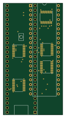 NXP
MCL6809
MicroCoreLabs
32.3 × 61 mm7 parts4LNo license532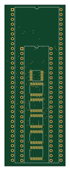 NXP
MCL68
31.6 × 84.1 mm13 parts4LNo license532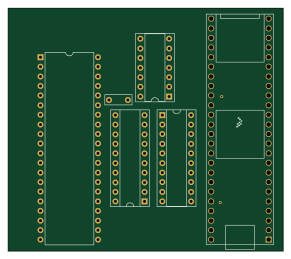 NXP
MCL65+
72.6 × 64.1 mm6 parts2LNo license532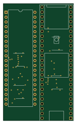 NXP
MCLZ8
37.1 × 61.5 mm6 parts4LNo license532