
Astable miltivibrator

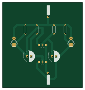
About the Astable miltivibrator PCB
Astable miltivibrator is an open source PCB design by JKCadilo14-CpE, published on GitHub under the MIT license. It is a 2-layer board measuring 71.1 × 76.2 mm, with 12 components from 7 distinct parts.
By type, the board carries 4 resistors, 2 transistors, 2 connectors, 2 diodes and 2 capacitors.
From the project
Collection of electronic circuits I designed, tested, and documented using KiCad
A beginner-friendly two-transistor astable multivibrator that alternates two LED outputs using cross-coupled transistor and capacitor stages.
This project demonstrates a classic astable multivibrator circuit. Two 2N3904 transistor stages are cross-coupled through timing capacitors and resistor networks so the LED outputs alternate.
The circuit is useful for learning transistor switching, capacitor charging behavior, polarized component orientation, breadboard-to-PCB troubleshooting, and basic oscillator concepts. It is an educational demonstration only and does not document a measured blink…
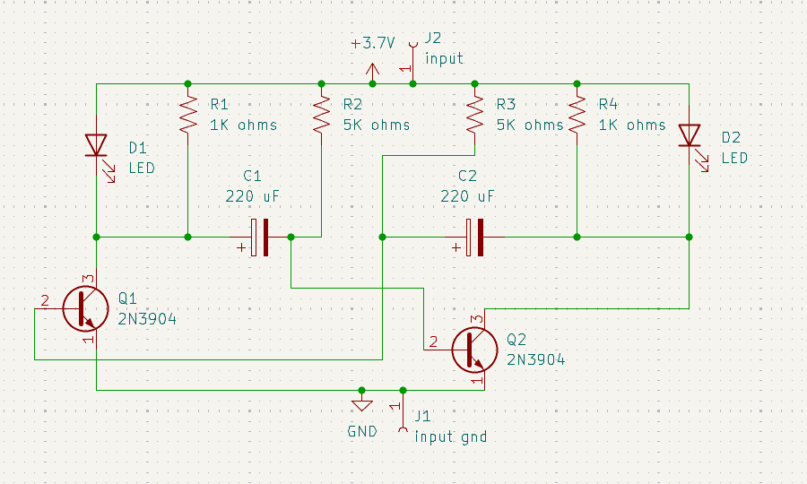
Astable miltivibrator bill of materials (BOM)
12 components, 7 distinct parts.
| Qty | Part | Footprint | Refs |
|---|---|---|---|
| 2 | 2N3904 | TO-92_Inline | Q1, Q2 |
| 1 | input gnd | PinSocket_1x01_P2.54mm_Horizontal | J1 |
| 1 | input | PinSocket_1x01_P2.54mm_Horizontal | J2 |
| 2 | LED | LED_D5.0mm | D1, D2 |
| 2 | 220 uF | CP_Radial_D10.0mm_P3.50mm | C1, C2 |
| 2 | 1K ohms | R_Axial_DIN0207_L6.3mm_D2.5mm_P7.62mm_Horizontal | R1, R4 |
| 2 | 5K ohms | R_Axial_DIN0207_L6.3mm_D2.5mm_P7.62mm_Horizontal | R2, R3 |
Astable miltivibrator design files
The KiCad project lives in the JKCadilo14-CpE/DIY-Circuits repository on GitHub; these links point at the commit this page was built from.
Astable miltivibrator: common questions
How big is the Astable miltivibrator PCB?
The Astable miltivibrator measures 71.1 × 76.2 mm, has 2 copper layers and is 1.6 mm thick.
How many components are on the Astable miltivibrator?
12 components, from 7 distinct parts. The full bill of materials is listed on this page.
Where can I download the Astable miltivibrator design files?
From the JKCadilo14-CpE/DIY-Circuits repository on GitHub, which has the KiCad layout and the schematic; the links under Design files point to each one.
Can I use the Astable miltivibrator design in my own project?
Yes, under the terms of its MIT license, which JKCadilo14-CpE chose for the repository.
More boards in DIY-Circuits

Water level indicator
101.6 × 71.1 mm18 parts2LMIT0
9V Battery Status Indicator Circuit
71.1 × 50.8 mm12 parts2LMIT0
Clap switch circuit
61 × 40.6 mm10 parts2LMIT0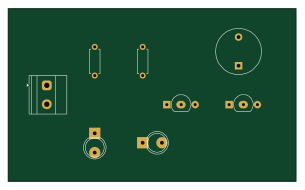
Obstacle detector
76.2 × 45.7 mm8 parts2LMIT0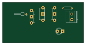
Hidden Wire Detector
71.1 × 35.6 mm7 parts2LMIT0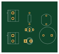
Laser Alarm Security Circuit
50.8 × 45.7 mm7 parts2LMIT0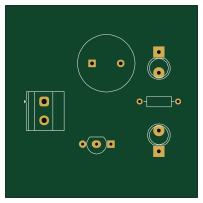
Fire alarm system using photodiode
50.8 × 50.8 mm6 parts2LMIT0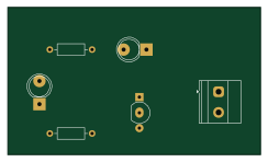
Light-Activated Switch
61 × 35.6 mm6 parts2LMIT0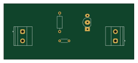
Temperature controlled dc fan
71.1 × 30.5 mm5 parts2LMIT0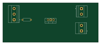
Automatic hand sanitizer
86.4 × 35.6 mm5 parts2LMIT0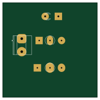
Touch sensor circuit
50.8 × 50.8 mm4 parts2LMIT0