
Clap switch circuit

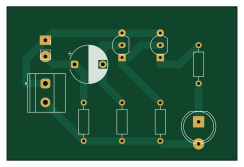
About the Clap switch circuit PCB
Clap switch circuit is an open source PCB design by JKCadilo14-CpE, published on GitHub under the MIT license. It is a 2-layer board measuring 61 × 40.6 mm, with 10 components from 9 distinct parts.
By type, the board carries 4 resistors, 2 transistors, 1 connector, 1 microphone, 1 diode and 1 capacitor.
From the project
Collection of electronic circuits I designed, tested, and documented using KiCad
A beginner-friendly sound-activated switching project using an electret condenser microphone, two BC547 transistor stages, and an LED output indicator.
This project demonstrates a simple clap-activated transistor circuit. A clap or sharp sound reaches the electret microphone, the signal is coupled through C1, transistor stages amplify or switch the response, and D1 provides the visible output indication.
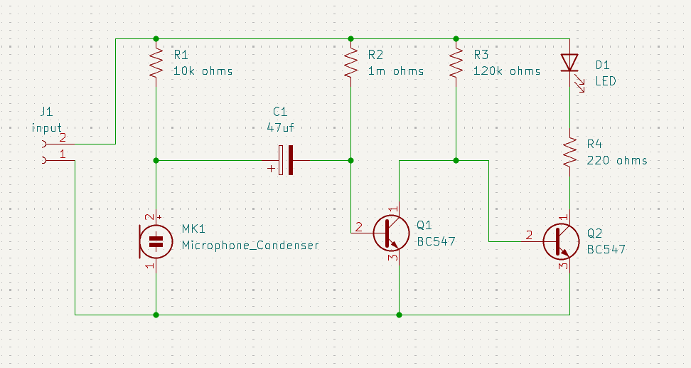
Clap switch circuit bill of materials (BOM)
10 components, 9 distinct parts.
| Qty | Part | Footprint | Refs |
|---|---|---|---|
| 2 | BC547 | TO-92_Inline | Q1, Q2 |
| 1 | input | TerminalBlock_Phoenix_MKDS-1,5-2_1x02_P5.00mm_Horizontal | J1 |
| 1 | Microphone_Condenser | PinSocket_1x02_P2.54mm_Vertical | MK1 |
| 1 | LED | LED_D8.0mm | D1 |
| 1 | 47uf | CP_Radial_D10.0mm_P7.50mm | C1 |
| 1 | 10k | R_Axial_DIN0207_L6.3mm_D2.5mm_P10.16mm_Horizontal | R1 |
| 1 | 1m | R_Axial_DIN0207_L6.3mm_D2.5mm_P10.16mm_Horizontal | R2 |
| 1 | 120k | R_Axial_DIN0207_L6.3mm_D2.5mm_P10.16mm_Horizontal | R3 |
| 1 | 220 | R_Axial_DIN0207_L6.3mm_D2.5mm_P10.16mm_Horizontal | R4 |
Clap switch circuit design files
The KiCad project lives in the JKCadilo14-CpE/DIY-Circuits repository on GitHub; these links point at the commit this page was built from.
Clap switch circuit: common questions
How big is the Clap switch circuit PCB?
The Clap switch circuit measures 61 × 40.6 mm, has 2 copper layers and is 1.6 mm thick.
How many components are on the Clap switch circuit?
10 components, from 9 distinct parts. The full bill of materials is listed on this page.
Where can I download the Clap switch circuit design files?
From the JKCadilo14-CpE/DIY-Circuits repository on GitHub, which has the KiCad layout and the schematic; the links under Design files point to each one.
Can I use the Clap switch circuit design in my own project?
Yes, under the terms of its MIT license, which JKCadilo14-CpE chose for the repository.
More boards in DIY-Circuits

Water level indicator
101.6 × 71.1 mm18 parts2LMIT0
Astable miltivibrator
71.1 × 76.2 mm12 parts2LMIT0
9V Battery Status Indicator Circuit
71.1 × 50.8 mm12 parts2LMIT0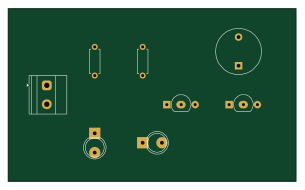
Obstacle detector
76.2 × 45.7 mm8 parts2LMIT0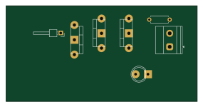
Hidden Wire Detector
71.1 × 35.6 mm7 parts2LMIT0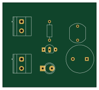
Laser Alarm Security Circuit
50.8 × 45.7 mm7 parts2LMIT0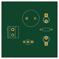
Fire alarm system using photodiode
50.8 × 50.8 mm6 parts2LMIT0
Light-Activated Switch
61 × 35.6 mm6 parts2LMIT0
Temperature controlled dc fan
71.1 × 30.5 mm5 parts2LMIT0
Automatic hand sanitizer
86.4 × 35.6 mm5 parts2LMIT0
Touch sensor circuit
50.8 × 50.8 mm4 parts2LMIT0