
3v3-charger psu

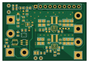
About the 3v3-charger psu PCB
3v3-charger psu is an open source PCB design by jvanderberg, published on GitHub. It is a 4-layer board measuring 44.3 × 31 mm, with 63 components from 37 distinct parts.
Other key parts include the BQ25185DLHR, TPS63070RNMR and DW01A_C351410. By type, the board carries 20 capacitors, 18 resistors, 9 connectors, 4 ICs, 4 test points and 3 diodes.
It belongs with the power & battery and sensors designs in this gallery.
From the project
USB-C 1S Li-ion charger and dual 3.3V/5V power module for embedded projects
The 3V3 Charger PSU is a compact internal power module for portable hobbyist electronics, combining USB-C charging, power-path management, and protection for a single 4.2 V Li-ion or LiPo battery. It provides independently controlled, always-regulated 3.3 V and 5 V outputs for microcontrollers, sensors, displays, radios, and other peripherals, with power-good signals, USB and battery monitoring, optional cell-temperature sensing, and low-power shutdown. The board is designed to mount inside a project with an enclosure-mounted USB-C connector and soldered or project-specific battery wiring…
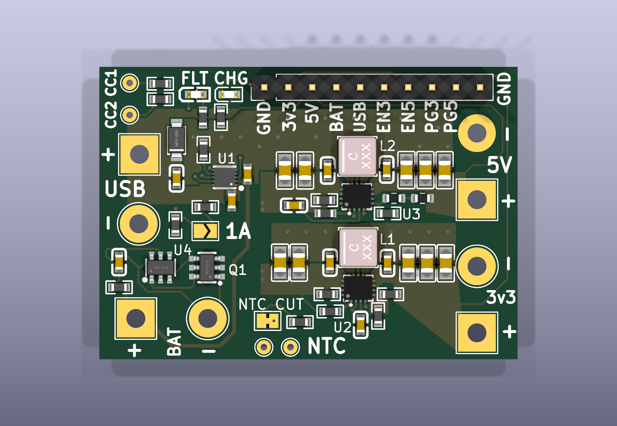
Main components on the 3v3-charger psu
3v3-charger psu bill of materials (BOM)
63 components, 37 distinct parts — part numbers from the project's BOM.
| Qty | Part | Footprint | Refs |
|---|---|---|---|
| 1 | BQ25185DLHR TI | BQ25185DLHR | U1 |
| 2 | TPS63070RNMR Texas Instruments | VQFN-HR-15_L3.0-W2.5-P0.50-BL_TPS63070RNMR | U2, U3 |
| 1 | DW01A_C351410 PUOLOP | DW01A_C351410 | U4 |
| 1 | FS8205A_C908265 FUXINSEMI | FS8205A_C908265 | Q1 |
| 1 | C57369 Breakout BOOMELE | PinHeader_1x10_P2.54mm_Vertical | J1 |
| 1 | VBUS | TestPoint_THTPad_4.0x4.0mm_Drill2.0mm | J2 |
| 3 | GND | TestPoint_THTPad_D4.0mm_Drill2.0mm | J3, J7, J9 |
| 1 | B+ | TestPoint_THTPad_4.0x4.0mm_Drill2.0mm | J4 |
| 1 | B- | TestPoint_THTPad_D4.0mm_Drill2.0mm | J5 |
| 1 | 3V3+ | TestPoint_THTPad_4.0x4.0mm_Drill2.0mm | J6 |
| 1 | 5V+ | TestPoint_THTPad_4.0x4.0mm_Drill2.0mm | J8 |
| 1 | RATE_1A | SolderJumper-2_P1.3mm_Open_TrianglePad1.0x1.5mm | JP1 |
| 1 | NTC_EMU | SolderJumper-2_P1.3mm_Bridged_Pad1.0x1.5mm | JP2 |
| 1 | CC1 | TestPoint_THTPad_D1.5mm_Drill0.7mm | TP1 |
| 1 | CC2 | TestPoint_THTPad_D1.5mm_Drill0.7mm | TP2 |
| 1 | NTC | TestPoint_THTPad_D1.5mm_Drill0.7mm | TP3 |
| 1 | NTC_GND | TestPoint_THTPad_D1.5mm_Drill0.7mm | TP4 |
| 1 | C111340 CHG KENTO | KT-0603O | D1 |
| 1 | C2286 FAULT KENTO | KT-0603R | D2 |
| 1 | SMF5.0A MDD | SMF5_0A_C193402 | D3 |
Show 17 more
| Qty | Part | Footprint | Refs |
|---|---|---|---|
| 2 | C3033018 1.5uH XFL4020 Coilcraft | XFL4020-152MEC | L1, L2 |
| 6 | C96446 10uF 25V SAMSUNG | CL10A106MA8NRNC | C1, C2, C7, C11, C15, C19 |
| 1 | 1UF 1uF SAMSUNG | CL10A105KB8NNNC | C3 |
| 3 | 100NF 100nF YAGEO | CC0603KRX7R9BB104 | C4, C12, C20 |
| 10 | 22UF 22uF FH | 0805X226M160NT | C5, C6, C8, C9, C10, C13, C14, C16 +2 |
| 2 | 560R UNI-ROYAL | 0603WAF5600T5E | R1, R2 |
| 1 | 13K 13k UNI-ROYAL | 0603WAF1302T5E | R3 |
| 3 | 10K 10k UNI-ROYAL | 0603WAF1002T5E | R4, R17, R18 |
| 2 | 1k UNI-ROYAL | 0603WAF1001T5E | R5, R6 |
| 2 | 5.1K 5.1k UNI-ROYAL | 0603WAF5101T5E | R7, R8 |
| 1 | 100R UNI-ROYAL | 0603WAF1000T5E | R9 |
| 1 | 470K 470k UNI-ROYAL | 0603WAF4703T5E | R10 |
| 1 | 150K 150k UNI-ROYAL | 0603WAF1503T5E | R11 |
| 2 | 1M UNI-ROYAL | 0603WAF1004T5E | R12, R15 |
| 1 | 330K 330k UNI-ROYAL(Uniroyal Elec) | R_0603_1608Metric | R13 |
| 1 | 100K 100k UNI-ROYAL | 0603WAF1003T5E | R14 |
| 1 | 200K 200k UNI-ROYAL(Uniroyal Elec) | R_0603_1608Metric | R16 |
3v3-charger psu design files
The KiCad project lives in the jvanderberg/3v3-charger-psu repository on GitHub; these links point at the commit this page was built from.
- Layout3v3ChargerPSU.kicad_pcb
- Schematic3v3ChargerPSU.kicad_sch
- BOMproduction/bom.csv
3v3-charger psu: common questions
How big is the 3v3-charger psu PCB?
The 3v3-charger psu measures 44.3 × 31 mm, has 4 copper layers and is 1.6 mm thick.
How many components are on the 3v3-charger psu?
63 components, from 37 distinct parts, with part numbers taken from the project's own BOM. The full bill of materials is listed on this page.
Where can I download the 3v3-charger psu design files?
From the jvanderberg/3v3-charger-psu repository on GitHub, which has the KiCad layout, the schematic and the BOM; the links under Design files point to each one.
Can I use the 3v3-charger psu design in my own project?
The repository has no license, so all rights stay with jvanderberg. Use it as a reference, and ask the author before reusing the design.
Similar boards

Sensor smd
scottbez1
40 × 20 mm5 parts2LApache-2.04.2k
Sensors
StuckAtPrototype
15.2 × 9 mm14 parts4LApache-2.03.8k
Stack chan
stack-chan
50 × 50 mm33 parts2LApache-2.01.7k
Display Carrier
AxxAxx
35.6 × 58.2 mm5 parts2LGPL-3.01.7k
Microphone
Mentra-Community
5.5 × 6.1 mm6 parts2LMIT1.2k
TemperaturePCB PANEL
stuartpittaway
116 × 75.5 mm178 parts2LCC-BY-NC-4.01.1k