
2040Inverter

About the 2040Inverter PCB
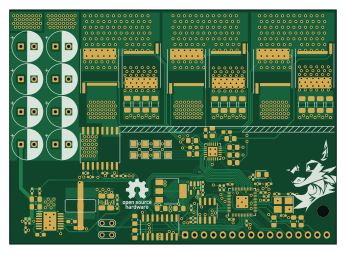
2040Inverter is an open source RP2040/RP2350 PCB design by Kirg5, published on GitHub. It is a 4-layer board measuring 86.4 × 61.9 mm, with 93 components from 35 distinct parts.
Its main chip is the RP2040, from the RP2040/RP2350 family. Other key parts include the MCR1101, DRV8300D, W25Q128JV, SPX3819M5-L-3-3 and LM5161PWP. By type, the board carries 47 capacitors, 28 resistors, 8 ICs, 6 transistors, 1 crystal and 1 connector.
It belongs with the robotics & motion, sensors and power & battery designs in this gallery.
From the project
RP2040 Based BLDC Inverter for sensored motors, capable of putting out 50a 100v
Development of this project has slowed due to firmware related complications and odd behaviour. In the current state, the firmware is able to rotate the motor, however attempting to log any data to a serial console causes crashes, communication with the display doesnt work, and there are loads of other issues with the entire system randomly locking up causing all mosfets to get stuck in whatever state they were previously in, which has caused hardware damage on multiple occasions. I have spent too much time trying to debug all of these things and have fully rewritten several times to no…
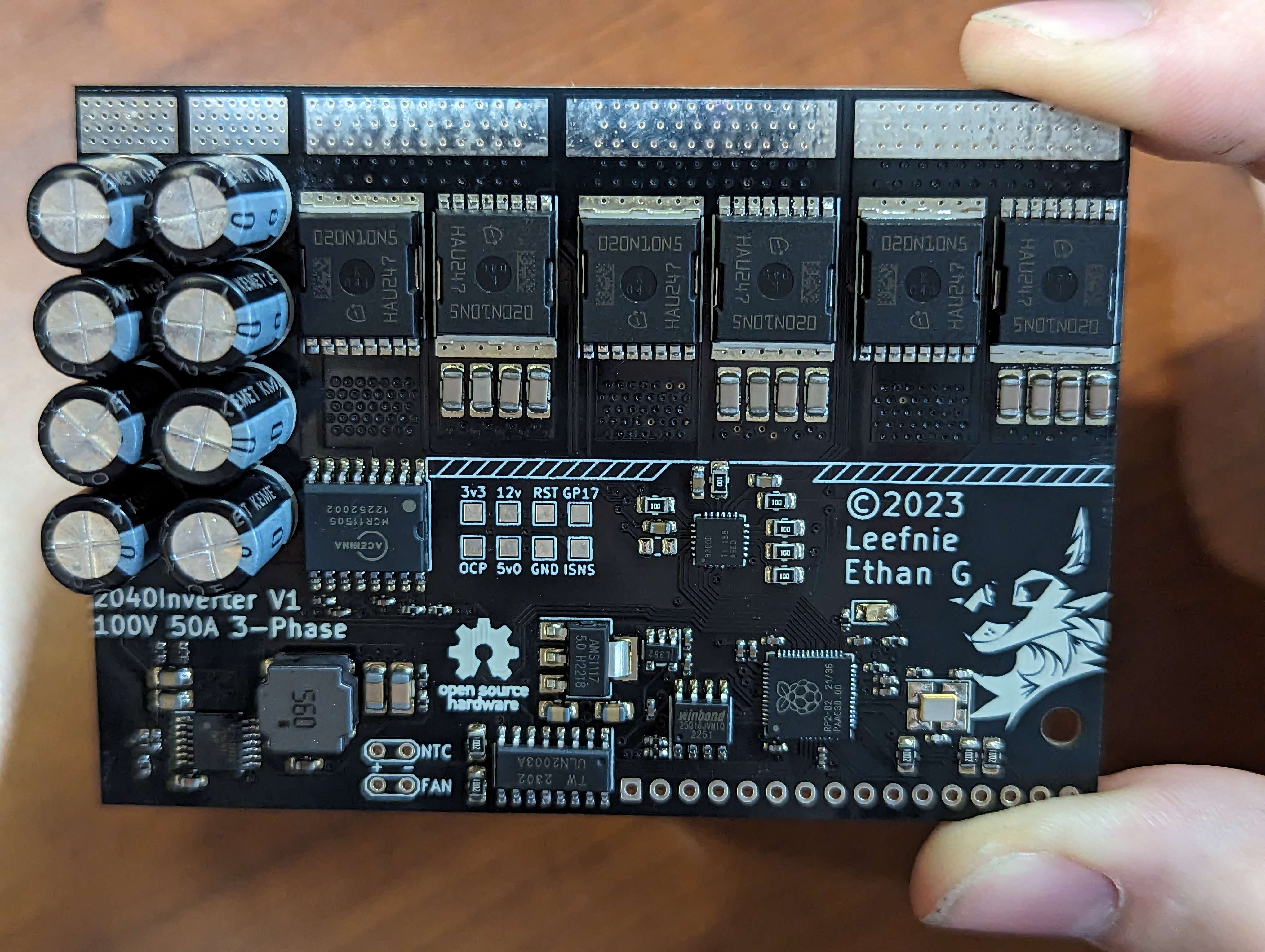
Main components on the 2040Inverter
2040Inverter bill of materials (BOM)
93 components, 35 distinct parts.
| Qty | Part | Footprint | Refs |
|---|---|---|---|
| 1 | MCR1101 | SOIC-16W_7.5x10.3mm_P1.27mm | U1 |
| 1 | RP2040 | QFN-56-1EP_7x7mm_P0.4mm_EP3.2x3.2mm | U2 |
| 1 | DRV8300D | VQFN-24-1EP_4x4mm_P0.5mm_EP2.5x2.5mm | U3 |
| 1 | W25Q128JV | SOIC-8-1EP_3.9x4.9mm_P1.27mm_EP2.29x3mm | U4 |
| 1 | SPX3819M5-L-3-3 | SOT-23-5 | U5 |
| 1 | LM5161PWP | HTSSOP-14-1EP_4.4x5mm_P0.65mm_EP3.4x5mm_Mask3x3.1mm | U7 |
| 1 | ULN2003A | SOIC-16_3.9x9.9mm_P1.27mm | U8 |
| 1 | AMS1117-5.0 | SOT-223-3_TabPin2 | U9 |
| 6 | Q_NMOS_GSD | Infineon_PG-HSOF-8-1 | Q1, Q2, Q3, Q4, Q5, Q6 |
| 1 | Wurth 830061647 | Crystal_SMD_3225-4Pin_3.2x2.5mm_HandSoldering | Y1 |
| 1 | Conn_01x16 | JST_XH_B16B-XH-A_1x16_P2.50mm_Vertical | J8 |
| 1 | BLUE | LED_0805_2012Metric_Pad1.15x1.40mm_HandSolder | D1 |
| 1 | 100µH | Wurth 74404084560 | L1 |
| 8 | 100uF, 100v | CP_Radial_D8.0mm_P3.50mm | C1, C2, C3, C4, C5, C6, C7, C8 |
| 13 | 100nF | C_0402_1005Metric_Pad0.74x0.62mm_HandSolder | C9, C10, C14, C15, C17, C19, C20, C21 +5 |
| 3 | 1uF, >50v | C_0603_1608Metric_Pad1.08x0.95mm_HandSolder | C11, C12, C13 |
| 2 | 10uF | C_0805_2012Metric_Pad1.18x1.45mm_HandSolder | C16, C47 |
| 12 | 10nF, 100v, C0G or NP0 dielectric | C_1206_3216Metric_Pad1.33x1.80mm_HandSolder | C18, C29, C30, C31, C32, C33, C34, C35 +4 |
| 2 | 12pF | C_0402_1005Metric_Pad0.74x0.62mm_HandSolder | C27, C28 |
| 1 | 1uF | C_0603_1608Metric_Pad1.08x0.95mm_HandSolder | C40 |
Show 15 more
| Qty | Part | Footprint | Refs |
|---|---|---|---|
| 1 | 22nF | C_0603_1608Metric_Pad1.08x0.95mm_HandSolder | C41 |
| 2 | 1uF, 100v | C_0805_2012Metric_Pad1.18x1.45mm_HandSolder | C42, C43 |
| 1 | 10nF | C_0603_1608Metric_Pad1.08x0.95mm_HandSolder | C44 |
| 2 | 10uF | C_1206_3216Metric_Pad1.33x1.80mm_HandSolder | C45, C46 |
| 1 | R_Small | R_0805_2012Metric_Pad1.20x1.40mm_HandSolder | R1 |
| 6 | 10 | R_0805_2012Metric_Pad1.20x1.40mm_HandSolder | R2, R3, R4, R5, R6, R7 |
| 2 | 1k | R_0402_1005Metric_Pad0.72x0.64mm_HandSolder | R8, R11 |
| 8 | 10K | R_0402_1005Metric_Pad0.72x0.64mm_HandSolder | R9, R10, R12, R15, R17, R18, R22, R25 |
| 5 | 10k | R_0805_2012Metric_Pad1.20x1.40mm_HandSolder | R13, R14, R16, R26, R27 |
| 1 | 162k | R_0402_1005Metric_Pad0.72x0.64mm_HandSolder | R19 |
| 1 | 75k | R_0402_1005Metric_Pad0.72x0.64mm_HandSolder | R20 |
| 1 | 1.37k | R_0402_1005Metric_Pad0.72x0.64mm_HandSolder | R21 |
| 1 | 2k | R_0402_1005Metric_Pad0.72x0.64mm_HandSolder | R23 |
| 1 | 320k | R_0402_1005Metric_Pad0.72x0.64mm_HandSolder | R24 |
| 1 | 330 | R_0402_1005Metric_Pad0.72x0.64mm_HandSolder | R28 |
2040Inverter design files
The KiCad project lives in the Kirg5/2040Inverter repository on GitHub; these links point at the commit this page was built from.
- LayoutPCB/inverter.kicad_pcb
- SchematicPCB/inverter.kicad_sch
2040Inverter: common questions
What microcontroller does the 2040Inverter use?
The 2040Inverter is built around the RP2040, from the RP2040/RP2350 family.
How big is the 2040Inverter PCB?
The 2040Inverter measures 86.4 × 61.9 mm, has 4 copper layers and is 1.6 mm thick.
How many components are on the 2040Inverter?
93 components, from 35 distinct parts. The full bill of materials is listed on this page.
Where can I download the 2040Inverter design files?
From the Kirg5/2040Inverter repository on GitHub, which has the KiCad layout and the schematic; the links under Design files point to each one.
Can I use the 2040Inverter design in my own project?
The repository has no license, so all rights stay with Kirg5. Use it as a reference, and ask the author before reusing the design.
Can I test firmware for the 2040Inverter without the hardware?
Yes. HardLabs builds a simulation of the board from its netlist and BOM, so you can run and debug RP2040/RP2350 firmware against it before you order a PCB.
Similar boards
 RP2040/RP2350
Open Book Abridged Edition
joeycastillo
85 × 115 mm29 parts2LCC-BY-SA-4.08.1k RP2040/RP2350
Corne
foostan
277.2 × 107.5 mm164 parts2LCC-BY-4.07.7k RP2040/RP2350
Corne
277.2 × 107.5 mm164 parts2LCC-BY-4.07.7k RP2040/RP2350
LogicAnalyzer
gusmanb
57 × 55.2 mm6 parts2LGPL-3.05.0k RP2040/RP2350
Jitx design
55.5 × 65 mm26 parts4LGPL-3.05.0k RP2040/RP2350
Pro V2
kata0510
290.1 × 130 mm270 parts2LMIT2.3k