
PortaPLUTO

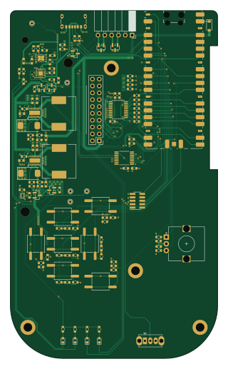
About the PortaPLUTO PCB
PortaPLUTO is an open source RP2040/RP2350 PCB design by kpezeshki, published on GitHub. It is a 4-layer board measuring 77 × 129 mm, with 135 components from 47 distinct parts.
Its main chip is the RaspberryPi_Pico, from the RP2040/RP2350 family. Other key parts include the BQ24075RGT, TSC2007IPWR, TPS63020, BQ27441-G1 and BQ297XY. By type, the board carries 57 resistors, 30 capacitors, 9 switches, 8 diodes, 7 ICs and 6 connectors.
It belongs with the power & battery designs in this gallery.
From the project
A handheld microwave analyzer based on the ADALM-PLUTO platform
This is a handheld microwave analyzer based on the PlutoSky, a variant of the ADALM-PLUTO SDR development platform. At a hardware level, it consists of a PlutoSky RF PCB, a system board, and user IO. The software integrates with Maia-SDR and iio to deliver basic microwave characterization functionality.
To build a portaPLUTO, you will need the following:
- a PlutoSky board. Buy one without the GPIO header, as you'll want pins of a different height - a mainboard PCB. JLCPCB stocks most of the components, but minor SMT hand assembly is required - an aluminum midplate. The Fusion file includes…
Main components on the PortaPLUTO
PortaPLUTO bill of materials (BOM)
135 components, 47 distinct parts — part numbers from the project's BOM.
| Qty | Part | Footprint | Refs |
|---|---|---|---|
| 1 | BQ24075RGT | VQFN-16-1EP_3x3mm_P0.5mm_EP1.6x1.6mm | U1 |
| 1 | TSC2007IPWR | SOP65P640X120-16N | U2 |
| 2 | TPS63020 | QFN14_1 | U3, U5 |
| 1 | BQ27441-G1 | Texas_S-PDSO-N12 | U4 |
| 1 | BQ297XY BQ297xy | WSON-6_1.5x1.5mm_P0.5mm | U6 |
| 1 | TXS0108EPW | TSSOP-20_4.4x6.5mm_P0.65mm | U7 |
| 1 | RaspberryPi_Pico | RaspberryPi_Pico_SMD_HandSolder | A2 |
| 2 | AO3401A | SOT-23 | Q1, Q4 |
| 2 | AO3400A | SOT-23 | Q2, Q3 |
| 1 | CONN_02X10_ODD_EVEN Conn_02x10_Odd_Even | PinHeader_2x10_P2.54mm_Vertical | J1 |
| 1 | CONN_01X50 Conn_01x50 | Amphenol_F32Q-1A7x1-11050_1x50-1MP_P0.5mm_Horizontal | J2 |
| 1 | Battery_Cell | BatteryHolder_Keystone_1042_1x18650 | J3 |
| 1 | CONN_01X06_PIN Conn_01x06_Pin | PinSocket_1x06_P2.54mm_Horizontal | J4 |
| 1 | USB_C_RECEPTACLE_POWERONLY_6P USB_C_Receptacle_PowerOnly_6P | USB_C_Receptacle_GCT_USB4125-xx-x-0190_6P_TopMnt_Horizontal | J5 |
| 1 | CONN_02X05_ODD_EVEN Conn_02x05_Odd_Even | PinSocket_2x05_P1.27mm_Vertical_SMD | J6 |
| 4 | JUMPER_2_BRIDGED Jumper_2_Bridged | SolderJumper-2_P1.3mm_Bridged_RoundedPad1.0x1.5mm | JP1, JP2, JP3, JP4 |
| 7 | SW_Push | SW_Push_1P1T_NO_CK_KSC6xxG | SW1, SW3, SW4, SW5, SW6, SW7, SW8 |
| 1 | RotaryEncoder | RotaryEncoder_Alps_EC12E_Vertical_H20mm | SW2 |
| 1 | SW_SPDT | SW_Slide_SPDT_Straight_CK_OS102011MS2Q | SW10 |
| 5 | TestPoint | TestPoint_THTPad_D1.5mm_Drill0.7mm | TP1, TP2, TP3, TP4, TP5 |
Show 27 more
| Qty | Part | Footprint | Refs |
|---|---|---|---|
| 4 | LED | LED_0603_1608Metric | D1, D2, D3, D4 |
| 1 | D_Schottky | D_SOD-123 | D5 |
| 3 | SP0502BAHT | SOT-23 | D6, D7, D8 |
| 2 | ~ | R_0603_1608Metric | FB1, FB2 |
| 2 | 1U2 1u2 | L_12x12mm_H4.5mm | L1, L2 |
| 4 | 100N 100n | C_0603_1608Metric | C1, C2, C9, C12 |
| 4 | 10U 10u | C_0603_1608Metric | C3, C4, C10, C11 |
| 2 | 100U 100u | CP_EIA-7343-31_Kemet-D | C5, C16 |
| 4 | ~ | C_0603_1608Metric | C6, C8, C13, C14 |
| 2 | 1u | C_0603_1608Metric | C7, C18 |
| 2 | 0.1U 0.1u | C_0603_1608Metric | C15, C20 |
| 2 | 4U7 4u7 | C_0603_1608Metric | C17, C21 |
| 1 | 0.47U 0.47u | C_0603_1608Metric | C19 |
| 9 | 10N 10n | C_0603_1608Metric | C22, C23, C24, C25, C26, C27, C28, C29 +1 |
| 6 | 10 | R_0603_1608Metric | R1, R2, R3, R4, R32, R33 |
| 1 | 1M6 | R_0603_1608Metric | R5 |
| 2 | 180K 180k | R_0603_1608Metric | R6, R9 |
| 16 | 10K 10k | R_0603_1608Metric | R7, R10, R13, R19, R20, R21, R22, R23 +8 |
| 1 | 1M | R_0603_1608Metric | R8 |
| 13 | 1k | R_0603_1608Metric | R11, R12, R14, R15, R43, R44, R51, R52 +5 |
| 1 | 10M 10m | R_0603_1608Metric | R16 |
| 4 | 5K1 5k1 | R_0603_1608Metric | R17, R18, R49, R50 |
| 7 | 0 | R_0603_1608Metric | R34, R35, R36, R37, R38, R39, R40 |
| 2 | 100K 100k | R_0603_1608Metric | R41, R42 |
| 1 | 330 | R_0603_1608Metric | R45 |
| 2 | 5M | R_0603_1608Metric | R46, R47 |
| 1 | 2K2 2k2 | R_0603_1608Metric | R48 |
PortaPLUTO design files
The KiCad project lives in the kpezeshki/portaPLUTO repository on GitHub; these links point at the commit this page was built from.
PortaPLUTO: common questions
What microcontroller does the PortaPLUTO use?
The PortaPLUTO is built around the RaspberryPi_Pico, from the RP2040/RP2350 family.
How big is the PortaPLUTO PCB?
The PortaPLUTO measures 77 × 129 mm, has 4 copper layers and is 1.6 mm thick.
How many components are on the PortaPLUTO?
135 components, from 47 distinct parts, with part numbers taken from the project's own BOM. The full bill of materials is listed on this page.
Where can I download the PortaPLUTO design files?
From the kpezeshki/portaPLUTO repository on GitHub, which has the KiCad layout, the schematic and the BOM; the links under Design files point to each one.
Can I use the PortaPLUTO design in my own project?
The repository has no license, so all rights stay with kpezeshki. Use it as a reference, and ask the author before reusing the design.
Can I test firmware for the PortaPLUTO without the hardware?
Yes. HardLabs builds a simulation of the board from its netlist and BOM, so you can run and debug RP2040/RP2350 firmware against it before you order a PCB.
Similar boards
 RP2040/RP2350
Open Book Abridged Edition
joeycastillo
85 × 115 mm29 parts2LCC-BY-SA-4.08.1k RP2040/RP2350
Corne
foostan
277.2 × 107.5 mm164 parts2LCC-BY-4.07.7k RP2040/RP2350
Corne
277.2 × 107.5 mm164 parts2LCC-BY-4.07.7k RP2040/RP2350
Jitx design
gusmanb
55.5 × 65 mm26 parts4LGPL-3.05.0k RP2040/RP2350
LogicAnalyzer
57 × 55.2 mm6 parts2LGPL-3.05.0k RP2040/RP2350
Main
google
98 × 71 mm102 parts2LApache-2.02.9k