
Esp32 Smart Plug

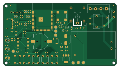
About the Esp32 Smart Plug PCB
Esp32 Smart Plug is an open source ESP32 PCB design by lalithk06, published on GitHub. It is a 2-layer board measuring 105 × 58 mm, with 70 components from 31 distinct parts.
Its main chip is the ESP32-S3-WROOM-1, from the ESP32 family. Other key parts include the AMS1117-3.3, USBLC6-2P6 and DS3231M. By type, the board carries 26 resistors, 16 capacitors, 7 diodes, 6 switches, 4 ICs and 3 connectors.
It belongs with the iot & wireless designs in this gallery.
From the project
Hardware reference design for an ESP32-S3 smart plug with mains power conversion, relay switching, RTC support, USB connectivity, and protection components. Built to explore real-world embedded hardware and power electronics design. The design is recreated for educational purposes to understand mains-powered embedded hardware.
This project presents the schematic and PCB design of a smart plug capable of switching AC loads while supporting modern embedded features such as USB connectivity, RTC support, and protection circuitry. Designed to explore real-world embedded hardware development and PCB design practices.
The system uses an ESP32-S3 microcontroller as the core processing unit. AC mains input is stepped down and regulated to provide safe DC power for the controller. A relay switching circuit enables the ESP32 to control connected appliances. Protection components safeguard the device against voltage spikes…
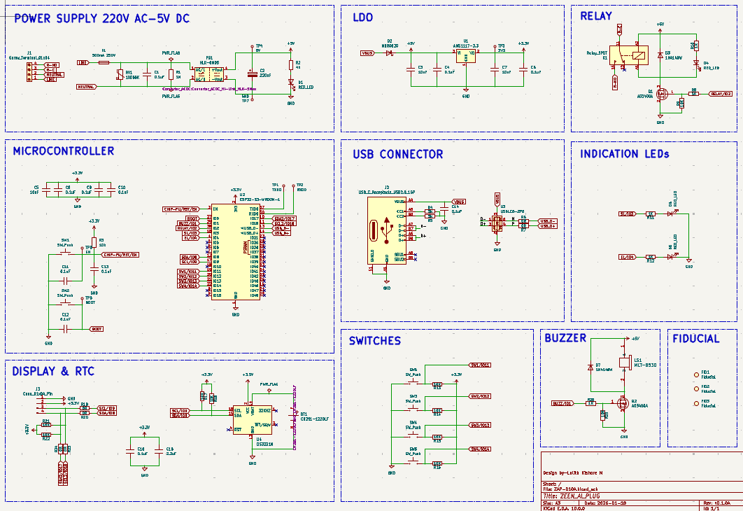
Main components on the Esp32 Smart Plug
Esp32 Smart Plug bill of materials (BOM)
70 components, 31 distinct parts.
| Qty | Part | Footprint | Refs |
|---|---|---|---|
| 1 | AMS1117-3.3 | SOT-223-3_TabPin2 | U1 |
| 1 | ESP32-S3-WROOM-1 | ESP32-S3-WROOM-1 | U2 |
| 1 | USBLC6-2P6 | SOT-666 | U3 |
| 1 | DS3231M | SOIC-16W_7.5x10.3mm_P1.27mm | U4 |
| 2 | AO3400A | SOT-23 | Q1, Q2 |
| 1 | Screw_Terminal_01x04 | TerminalBlock_MaiXu_MX126-5.0-04P_1x04_P5.00mm | J1 |
| 1 | USB_C_Receptacle_USB2.0_16P | USB_C_Receptacle_HCTL_HC-TYPE-C-16P-01A | J2 |
| 1 | Conn_01x04_Pin | PinHeader_1x04_P2.54mm_Vertical | J3 |
| 1 | CH291-1220LF | BAT_CH291-1220LF | BT1 |
| 1 | 500mA 250V | Fuse_Littelfuse_395Series | F1 |
| 1 | Relay_SPDT | Relay_SPDT_Hongfa_HF3F-L-xx-1ZL1T | K1 |
| 1 | MLT-8530 | MLT-8530_JHE | LS1 |
| 1 | HLK-5M05 | Converter_ACDC_Hi-Link_HLK-5Mxx | PS1 |
| 1 | 10D56K | RV_Disc_D12mm_W5.8mm_P7.5mm | RV1 |
| 5 | SW_Push | SW_PUSH_6mm | SW1, SW3, SW4, SW5, SW6 |
| 1 | SW_Push | SW_Push_SPST_NO_Alps_SKRK | SW2 |
| 3 | RED_LED | LED_D3.0mm | D1, D5, D6 |
| 1 | MBR0520 | D_SOD-123 | D2 |
| 2 | 1N4148W | D_SOD-123 | D3, D7 |
| 1 | RED_LED | LED_0603_1608Metric_Pad1.05x0.95mm_HandSolder | D4 |
Show 11 more
| Qty | Part | Footprint | Refs |
|---|---|---|---|
| 1 | 0.1uF | C_Rect_L13.0mm_W6.0mm_P10.00mm_FKS3_FKP3_MKS4 | C1 |
| 1 | 220uF | CP_Elec_8x10 | C2 |
| 3 | 10uF | C_0805_2012Metric | C3, C5, C7 |
| 10 | 0.1uF | C_0603_1608Metric | C4, C6, C8, C9, C10, C11, C12, C13 +2 |
| 1 | 2.2uF | C_0805_2012Metric | C16 |
| 1 | 1M | R_Axial_DIN0204_L3.6mm_D1.6mm_P5.08mm_Horizontal | R1 |
| 1 | 4k | R_0603_1608Metric | R2 |
| 11 | 10K | R_0603_1608Metric | R3, R9, R13, R14, R15, R16, R17, R18 +3 |
| 2 | 5k | R_0603_1608Metric | R4, R5 |
| 6 | 0R | R_0603_1608Metric | R6, R7, R19, R20, R23, R24 |
| 5 | 1K | R_0603_1608Metric | R8, R10, R11, R12, R26 |
Esp32 Smart Plug design files
The KiCad project lives in the lalithk06/Esp32_Smart_Plug repository on GitHub; these links point at the commit this page was built from.
Esp32 Smart Plug: common questions
What microcontroller does the Esp32 Smart Plug use?
The Esp32 Smart Plug is built around the ESP32-S3-WROOM-1, from the ESP32 family.
How big is the Esp32 Smart Plug PCB?
The Esp32 Smart Plug measures 105 × 58 mm, has 2 copper layers and is 1.6 mm thick.
How many components are on the Esp32 Smart Plug?
70 components, from 31 distinct parts. The full bill of materials is listed on this page.
Where can I download the Esp32 Smart Plug design files?
From the lalithk06/Esp32_Smart_Plug repository on GitHub, which has the KiCad layout and the schematic; the links under Design files point to each one.
Can I use the Esp32 Smart Plug design in my own project?
The repository has no license, so all rights stay with lalithk06. Use it as a reference, and ask the author before reusing the design.
Can I test firmware for the Esp32 Smart Plug without the hardware?
Yes. HardLabs builds a simulation of the board from its netlist and BOM, so you can run and debug ESP32 firmware against it before you order a PCB.
Similar boards
 ESP32
ESP32Open Book Abridged Edition
joeycastillo
85 × 115 mm65 parts2LCC-BY-SA-4.08.1k ESP32
ESP32Badge
atopile
56.3 × 39 mm239 parts4LMIT4.0k ESP32
ESP32Esp32 minimal
36.2 × 26.8 mm20 parts2LMIT4.0k ESP32
ESP32Racer
StuckAtPrototype
36 × 50.2 mm70 parts4LApache-2.03.8k ESP32
ESP32Controller
29 × 74 mm58 parts4LApache-2.03.8k ESP32
ESP32Bitaxe
skot
56.5 × 99.8 mm86 parts4LCERN-OHL-S-2.01.4k