
Test jig

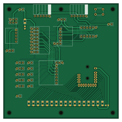
About the Test jig PCB
Test jig is an open source PCB design by laneboysrc, published on GitHub under the MIT license. It is a 2-layer board measuring 100 × 100 mm, with 54 components from 54 distinct parts.
By type, the board carries 32 connectors, 18 diodes, 2 switches and 2 resistors.
It belongs with the rf & radio designs in this gallery.
From the project
Extensible RC car light controller with Web-based configuration tool
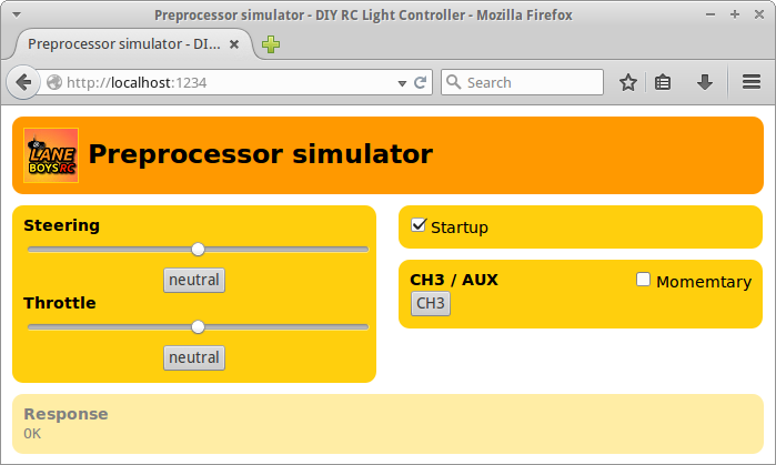
The command line tools are writing in Python.
Reads and displays the output of the preprocessor (= a small microcontroller that interfaces with your receiver. This microcontroller outputs a single serial signal containing information for steering, servo and AUX channels. By using a preprocessor the light controller can be connected with a single servo extension wire.)
Test jig bill of materials (BOM)
54 components, 54 distinct parts — part numbers from the project's BOM.
| Qty | Part | Footprint | Refs |
|---|---|---|---|
| 1 | POWER | PinHeader_1x03_P2.54mm_Vertical | J1 |
| 1 | USB_B_Micro | PinHeader_1x05_P2.54mm_Horizontal | J2 |
| 1 | RXe_AUX3 | PinHeader_1x03_P2.54mm_Vertical | J3 |
| 1 | RXe_AUX2 | PinHeader_1x03_P2.54mm_Vertical | J4 |
| 1 | RXe_AUX | PinHeader_1x03_P2.54mm_Vertical | J5 |
| 1 | RXe_TH | PinHeader_1x03_P2.54mm_Vertical | J6 |
| 1 | RXe_ST | PinHeader_1x03_P2.54mm_Vertical | J7 |
| 1 | RX8CH_S_PLUS | PinSocket_1x03_P2.54mm_Vertical | J8 |
| 1 | RX8CH_S | PinSocket_1x07_P2.54mm_Vertical | J9 |
| 1 | PP3CH_GND_PLUS_S | PinSocket_1x03_P2.54mm_Vertical | J10 |
| 1 | PP3CH_S | PinSocket_1x05_P2.54mm_Vertical | J11 |
| 1 | PP8CH_ST1 | PinSocket_1x03_P2.54mm_Vertical | J12 |
| 1 | PP8CH_ST2 | PinSocket_1x03_P2.54mm_Vertical | J13 |
| 1 | PP8CH_TH1 | PinSocket_1x03_P2.54mm_Vertical | J14 |
| 1 | PP8CH_TH2 | PinSocket_1x03_P2.54mm_Vertical | J15 |
| 1 | PP8CH_AUX | PinSocket_1x03_P2.54mm_Vertical | J16 |
| 1 | PP8CH_AUX2 | PinSocket_1x03_P2.54mm_Vertical | J17 |
| 1 | PP8CH_AUX3 | PinSocket_1x03_P2.54mm_Vertical | J18 |
| 1 | PP8CH_Light | PinSocket_1x03_P2.54mm_Vertical | J19 |
| 1 | TP_PLUS | PinHeader_1x02_P2.54mm_Vertical | J20 |
Show 34 more
| Qty | Part | Footprint | Refs |
|---|---|---|---|
| 1 | TP_GND | PinHeader_1x02_P2.54mm_Vertical | J21 |
| 1 | TP_ST | PinHeader_1x02_P2.54mm_Vertical | J22 |
| 1 | TP_TH | PinHeader_1x02_P2.54mm_Vertical | J23 |
| 1 | TP_AUX | PinHeader_1x02_P2.54mm_Vertical | J24 |
| 1 | TP_AUX2 | PinHeader_1x02_P2.54mm_Vertical | J25 |
| 1 | TP_AUX3 | PinHeader_1x02_P2.54mm_Vertical | J26 |
| 1 | TP_Light | PinHeader_1x02_P2.54mm_Vertical | J27 |
| 1 | TP_OUT_ISP | PinHeader_1x03_P2.54mm_Vertical | J28 |
| 1 | UART_PP | PinSocket_1x06_P2.54mm_Horizontal | J29 |
| 1 | UART_LC | PinSocket_1x06_P2.54mm_Horizontal | J30 |
| 1 | LC_PP | PinHeader_1x06_P2.54mm_Vertical | J31 |
| 1 | LC_SERVO | PinHeader_1x06_P2.54mm_Vertical | J32 |
| 1 | On/Off | PinSocket_2x03_P2.54mm_Vertical | SW1 |
| 1 | SW_AUX | SW_PUSH_6mm_H5mm | SW2 |
| 1 | LED_POWER | LED_1206_3216Metric_Pad1.42x1.75mm_HandSolder | D1 |
| 1 | 0 | LED_1206_3216Metric_Pad1.42x1.75mm_HandSolder | D2 |
| 1 | 1 | LED_1206_3216Metric_Pad1.42x1.75mm_HandSolder | D3 |
| 1 | 2 | LED_1206_3216Metric_Pad1.42x1.75mm_HandSolder | D4 |
| 1 | 3 | LED_1206_3216Metric_Pad1.42x1.75mm_HandSolder | D5 |
| 1 | 4 | LED_1206_3216Metric_Pad1.42x1.75mm_HandSolder | D6 |
| 1 | 5 | LED_1206_3216Metric_Pad1.42x1.75mm_HandSolder | D7 |
| 1 | 6 | LED_1206_3216Metric_Pad1.42x1.75mm_HandSolder | D8 |
| 1 | 7 | LED_1206_3216Metric_Pad1.42x1.75mm_HandSolder | D9 |
| 1 | 8 | LED_1206_3216Metric_Pad1.42x1.75mm_HandSolder | D10 |
| 1 | 9 | LED_1206_3216Metric_Pad1.42x1.75mm_HandSolder | D11 |
| 1 | 10 | LED_1206_3216Metric_Pad1.42x1.75mm_HandSolder | D12 |
| 1 | 11 | LED_1206_3216Metric_Pad1.42x1.75mm_HandSolder | D13 |
| 1 | 12 | LED_1206_3216Metric_Pad1.42x1.75mm_HandSolder | D14 |
| 1 | 13 | LED_1206_3216Metric_Pad1.42x1.75mm_HandSolder | D15 |
| 1 | 14 | LED_1206_3216Metric_Pad1.42x1.75mm_HandSolder | D16 |
| 1 | 15 | LED_1206_3216Metric_Pad1.42x1.75mm_HandSolder | D17 |
| 1 | 15S | LED_1206_3216Metric_Pad1.42x1.75mm_HandSolder | D18 |
| 1 | 680 | R_0805_2012Metric_Pad1.15x1.40mm_HandSolder | R1 |
| 1 | 220 | R_0805_2012Metric_Pad1.15x1.40mm_HandSolder | R2 |
Test jig design files
The KiCad project lives in the laneboysrc/rc-light-controller repository on GitHub; these links point at the commit this page was built from.
Test jig: common questions
How big is the Test jig PCB?
The Test jig measures 100 × 100 mm, has 2 copper layers and is 1.6 mm thick.
How many components are on the Test jig?
54 components, from 54 distinct parts, with part numbers taken from the project's own BOM. The full bill of materials is listed on this page.
Where can I download the Test jig design files?
From the laneboysrc/rc-light-controller repository on GitHub, which has the KiCad layout and the BOM; the links under Design files point to each one.
Can I use the Test jig design in my own project?
Yes, under the terms of its MIT license, which laneboysrc chose for the repository.
More boards in rc-light-controller
 NXP
NXPRc light controller tlc5940-lpc832-sbus
29 × 18 mm36 partsMIT87 NXP
NXPRc light controller switching
44 × 23 mm18 parts2LMIT87 WCH CH32/CH55x
Webusb programmer rev6
38 × 20 mm18 parts2LMIT87 NXP
NXPPreprocessor multi aux lpc832
17 × 24 mm15 parts2LMIT87 NXP
NXPRc light controller pinheader
44 × 23 mm12 parts2LMIT87 NXP
NXPPreprocessor-3ch lpc832
17 × 17 mm11 parts2LMIT87
Similar boards

Hat
pa3gsb
65 × 56 mm81 parts2LNo license675
Radioberry preamp
65 × 56 mm137 parts2LNo license675
Radioberry juice
65 × 56 mm87 parts2LNo license675
Goodwatch30
travisgoodspeed
25.6 × 27.6 mm23 parts2LNo license568
GoodPocketWatch
75.2 × 101.2 mm56 parts2LNo license568
Goodwatch31
25.6 × 27.6 mm23 parts2LNo license568