
VCAT-VehicleControlUnit

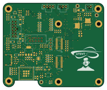
About the VCAT-VehicleControlUnit PCB
VCAT-VehicleControlUnit is an open source ESP32 PCB design by lhr-solar, published on GitHub under the MIT license. It is a 2-layer board measuring 86.6 × 71.8 mm, with 122 components from 47 distinct parts.
Its main chip is the ESP32-C6-MINI-1/U, from the ESP32 family. Other key parts include the LM74502HDDFR, TPS2115ADRBR and LT1963AEST-3.3#TRPBF. By type, the board carries 52 resistors, 24 LEDs, 22 capacitors, 11 diodes, 6 transistors and 4 ICs.
It belongs with the power & battery designs in this gallery.
From the project
Vehicle Control Unit (VCU) for the 2026 Longhorn Racing Solar car
This will place you in a nix shell with all needed dependencies. After the first time, you only need to run the below command to enter the nix shell.
To compile production firmware, simply run:
Test files are located in test/ and must have the prefix test or else the test won't compile correctly. If you want to run the blinky test, which is located in tests/blinkytest.c` you will run
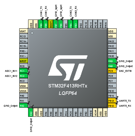
Main components on the VCAT-VehicleControlUnit
VCAT-VehicleControlUnit bill of materials (BOM)
122 components, 47 distinct parts.
| Qty | Part | Footprint | Refs |
|---|---|---|---|
| 1 | LM74502HDDFR | SOT65P280X110-8N | IC1 |
| 1 | TPS2115ADRBR | SON65P300X300X100-9N | U2 |
| 1 | LT1963AEST-3.3#TRPBF | SOT-223-3_TabPin2 | U3 |
| 1 | ESP32-C6-MINI-1/U | ESP32-C6-MINI-1 | U4 |
| 4 | IRLML0030 | SOT-23 | Q1, Q2, Q3, Q4 |
| 2 | NVMFWS1D7N04XMT1G | NVMFWS3D0P04M8LT1G | Q5, Q6 |
| 2 | LED | LED_0603_1608Metric_Pad1.05x0.95mm_HandSolder | Con1, Con2 |
| 1 | USB_C_Receptacle_USB2.0_16P | USB_C_Receptacle_GCT_USB4105-xx-A_16P_TopMnt_Horizontal | J6 |
| 2 | HB | LED_0603_1608Metric_Pad1.05x0.95mm_HandSolder | LV1, LV17 |
| 1 | FLASH | LED_0603_1608Metric_Pad1.05x0.95mm_HandSolder | LV2 |
| 1 | ERR | LED_0603_1608Metric_Pad1.05x0.95mm_HandSolder | LV3 |
| 1 | BLE | LED_0603_1608Metric_Pad1.05x0.95mm_HandSolder | LV4 |
| 1 | PC | LED_0603_1608Metric_Pad1.05x0.95mm_HandSolder | LV5 |
| 2 | PT | LED_0603_1608Metric_Pad1.05x0.95mm_HandSolder | LV6, LV23 |
| 1 | ST | LED_0603_1608Metric_Pad1.05x0.95mm_HandSolder | LV7 |
| 1 | MF | LED_0603_1608Metric_Pad1.05x0.95mm_HandSolder | LV8 |
| 1 | BF | LED_0603_1608Metric_Pad1.05x0.95mm_HandSolder | LV9 |
| 1 | SWOC | LED_0603_1608Metric_Pad1.05x0.95mm_HandSolder | LV10 |
| 1 | MW | LED_0603_1608Metric_Pad1.05x0.95mm_HandSolder | LV11 |
| 1 | HALL | LED_0603_1608Metric_Pad1.05x0.95mm_HandSolder | LV12 |
Show 27 more
| Qty | Part | Footprint | Refs |
|---|---|---|---|
| 1 | LED1 | LED_0603_1608Metric_Pad1.05x0.95mm_HandSolder | LV13 |
| 1 | LED2 | LED_0603_1608Metric_Pad1.05x0.95mm_HandSolder | LV14 |
| 1 | LED3 | LED_0603_1608Metric_Pad1.05x0.95mm_HandSolder | LV15 |
| 1 | LED4 | LED_0603_1608Metric_Pad1.05x0.95mm_HandSolder | LV16 |
| 1 | Regen | LED_0603_1608Metric_Pad1.05x0.95mm_HandSolder | LV18 |
| 1 | Cruise | LED_0603_1608Metric_Pad1.05x0.95mm_HandSolder | LV19 |
| 1 | Safe | LED_0603_1608Metric_Pad1.05x0.95mm_HandSolder | LV20 |
| 2 | Driving | LED_0603_1608Metric_Pad1.05x0.95mm_HandSolder | LV21, LV22 |
| 1 | LED | LED_0603_1608Metric_Pad1.05x0.95mm_HandSolder | LVPWR1 |
| 2 | TVS | D_SOD-123F | D1, D2 |
| 1 | 1N5819HW-7-F | D_SOD-123 | D3 |
| 1 | SP0503BAHT | SOT-143 | D4 |
| 4 | PWR | LED_0603_1608Metric_Pad1.05x0.95mm_HandSolder | D5, D6, D7, D8 |
| 2 | D | SODFL4724X108N | D9, D10 |
| 1 | SMAF4758A | SODFL5026X125N | D11 |
| 11 | 0.1u | C_0603_1608Metric_Pad1.08x0.95mm_HandSolder | C1, C2, C6, C7, C9, C11, C13, C15 +3 |
| 6 | 10u | C_0805_2012Metric_Pad1.18x1.45mm_HandSolder | C3, C4, C5, C8, C17, C18 |
| 4 | 1u | C_0603_1608Metric_Pad1.08x0.95mm_HandSolder | C10, C12, C14, C20 |
| 1 | 220n | C_0603_1608Metric_Pad1.08x0.95mm_HandSolder | C16 |
| 24 | 1k | R_0603_1608Metric_Pad0.98x0.95mm_HandSolder | R1, R15, R24, R32, R33, R34, R35, R36 +16 |
| 13 | 10k | R_0603_1608Metric_Pad0.98x0.95mm_HandSolder | R2, R8, R10, R11, R12, R13, R17, R18 +5 |
| 2 | 5.1k | R_0603_1608Metric_Pad0.98x0.95mm_HandSolder | R3, R4 |
| 1 | 450 | R_0603_1608Metric_Pad0.98x0.95mm_HandSolder | R5 |
| 7 | 120 | R_0603_1608Metric_Pad0.98x0.95mm_HandSolder | R6, R7, R9, R16, R19, R20, R21 |
| 3 | 4.3k | R_0603_1608Metric_Pad0.98x0.95mm_HandSolder | R14, R25, R31 |
| 1 | 200k | R_0603_1608Metric_Pad0.98x0.95mm_HandSolder | R29 |
| 1 | 9k | R_0603_1608Metric_Pad0.98x0.95mm_HandSolder | R30 |
VCAT-VehicleControlUnit design files
The KiCad project lives in the lhr-solar/VCAT-VehicleControlUnit repository on GitHub; these links point at the commit this page was built from.
VCAT-VehicleControlUnit: common questions
What microcontroller does the VCAT-VehicleControlUnit use?
The VCAT-VehicleControlUnit is built around the ESP32-C6-MINI-1/U, from the ESP32 family.
How big is the VCAT-VehicleControlUnit PCB?
The VCAT-VehicleControlUnit measures 86.6 × 71.8 mm, has 2 copper layers and is 1.6 mm thick.
How many components are on the VCAT-VehicleControlUnit?
122 components, from 47 distinct parts. The full bill of materials is listed on this page.
Where can I download the VCAT-VehicleControlUnit design files?
From the lhr-solar/VCAT-VehicleControlUnit repository on GitHub, which has the KiCad layout and the schematic; the links under Design files point to each one.
Can I use the VCAT-VehicleControlUnit design in my own project?
Yes, under the terms of its MIT license, which lhr-solar chose for the repository.
Can I test firmware for the VCAT-VehicleControlUnit without the hardware?
Yes. HardLabs builds a simulation of the board from its netlist and BOM, so you can run and debug ESP32 firmware against it before you order a PCB.
Similar boards
 ESP32
ESP32Open Book Abridged Edition
joeycastillo
85 × 115 mm65 parts2LCC-BY-SA-4.08.1k ESP32
ESP32Badge
atopile
56.3 × 39 mm239 parts4LMIT4.0k ESP32
ESP32Esp32 minimal
36.2 × 26.8 mm20 parts2LMIT4.0k ESP32
ESP32Racer
StuckAtPrototype
36 × 50.2 mm70 parts4LApache-2.03.8k ESP32
ESP32Controller
29 × 74 mm58 parts4LApache-2.03.8k ESP32
ESP32Bitaxe
skot
56.5 × 99.8 mm86 parts4LCERN-OHL-S-2.01.4k