
Esp32solder

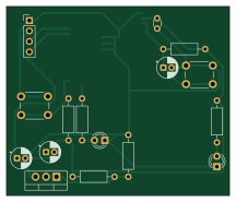
About the Esp32solder PCB
Esp32solder is an open source ESP32 PCB design by MadsRudolph, published on GitHub. It is a 2-layer board measuring 54 × 45.8 mm, with 17 components from 15 distinct parts.
Its main chip is the TL074, from the ESP32 family. Other key parts include the LM7812. By type, the board carries 6 resistors, 4 capacitors, 2 ICs, 2 switches, 2 diodes and 1 connector.
It belongs with the iot & wireless designs in this gallery.
From the project
This is the smallest board that proves an ESP32-WROOM-32 hand-soldered to copper etched on the xTool F1 Ultra actually works. Once it's soldered, you flash it over a USB-UART adapter and blink the LED on IO2. Everything except the module is through-hole and stocked at the DTU com
This is the smallest board that proves an ESP32-WROOM-32 hand-soldered to copper etched on the xTool F1 Ultra actually works. Once it's soldered, you flash it over a USB-UART adapter and blink the LED on IO2. Everything except the module is through-hole and stocked at the DTU component shop.
- Single-sided, 54 x 46 mm, copper on the bottom (B.Cu). The ESP32 sits on the copper side and the through-hole parts go on top. - Rule: 0.3 mm clearance / 0.5 mm track, inside what the test coupon proved (0.15 / 0.15 clean). - Gates: - Schematic: schscore` PASS, ERC 0 violations, netlist verified. -…
Main components on the Esp32solder
Esp32solder bill of materials (BOM)
17 components, 15 distinct parts — part numbers from the project's BOM.
| Qty | Part | Footprint | Refs |
|---|---|---|---|
| 1 | TL074 ESP32-WROOM-32 | ESP32-WROOM-32_NoVias | U1 |
| 1 | LM7812 LM317T | TO-220-3_Vertical | U2 |
| 1 | UART / 5V | PinHeader_1x04_P2.54mm_Vertical | J1 |
| 1 | RESET | SW_PUSH_6mm | SW1 |
| 1 | BOOT | SW_PUSH_6mm | SW2 |
| 1 | LED green | LED_D3.0mm | D1 |
| 1 | LED red | LED_D3.0mm | D2 |
| 2 | 10u | CP_Radial_D5.0mm_P2.00mm | C1, C2 |
| 1 | 100n | C_Disc_D3.0mm_W1.6mm_P2.50mm | C3 |
| 1 | 1u | CP_Radial_D5.0mm_P2.00mm | C4 |
| 1 | 243 | R_Axial_DIN0207_L6.3mm_D2.5mm_P10.16mm_Horizontal | R1 |
| 1 | 8K25 392 | R_Axial_DIN0207_L6.3mm_D2.5mm_P10.16mm_Horizontal | R2 |
| 2 | 10K 10k | R_Axial_DIN0207_L6.3mm_D2.5mm_P10.16mm_Horizontal | R3, R4 |
| 1 | 100R 332 | R_Axial_DIN0207_L6.3mm_D2.5mm_P10.16mm_Horizontal | R5 |
| 1 | 100R 1k | R_Axial_DIN0207_L6.3mm_D2.5mm_P10.16mm_Horizontal | R6 |
Esp32solder design files
The KiCad project lives in the MadsRudolph/personal-projects repository on GitHub; these links point at the commit this page was built from.
Esp32solder: common questions
What microcontroller does the Esp32solder use?
The Esp32solder is built around the TL074, from the ESP32 family.
How big is the Esp32solder PCB?
The Esp32solder measures 54 × 45.8 mm, has 2 copper layers and is 1.6 mm thick.
How many components are on the Esp32solder?
17 components, from 15 distinct parts, with part numbers taken from the project's own BOM. The full bill of materials is listed on this page.
Where can I download the Esp32solder design files?
From the MadsRudolph/personal-projects repository on GitHub, which has the KiCad layout, the schematic and the BOM; the links under Design files point to each one.
Can I use the Esp32solder design in my own project?
The repository has no license, so all rights stay with MadsRudolph. Use it as a reference, and ask the author before reusing the design.
Can I test firmware for the Esp32solder without the hardware?
Yes. HardLabs builds a simulation of the board from its netlist and BOM, so you can run and debug ESP32 firmware against it before you order a PCB.
More boards in personal-projects
 AVR/Arduino
Multimeter
688 × 275.9 mm62 parts2LNo license0
Classd.refined
190.5 × 104 mm61 parts2LNo license0
Classd.autoplaced.refined.routed
190.5 × 104 mm61 parts2LNo license0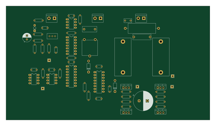
Classd
186.5 × 104 mm61 parts2LNo license0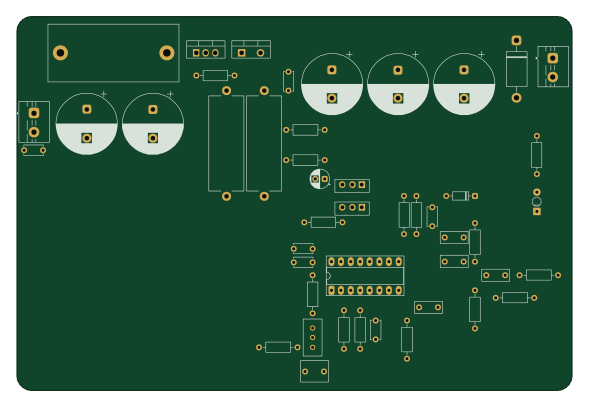
Monitor boost
147 × 99 mm47 parts2LNo license0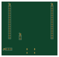 ESP32
ESP32Esp32node
63 × 60.8 mm32 parts2LNo license0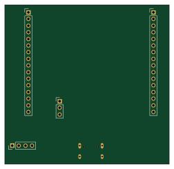 ESP32
ESP32Esp32node wip
63 × 60.8 mm32 parts2LNo license0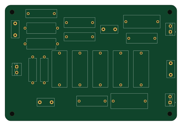
Illuminate7mk2-crossover
148 × 100 mm23 parts2LNo license0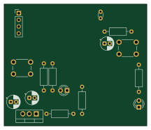 ESP32
ESP32Esp32solder.placed
54 × 45.8 mm17 parts2LNo license0
Similar boards
 ESP32
ESP32Open Book Abridged Edition
joeycastillo
85 × 115 mm65 parts2LCC-BY-SA-4.08.1k ESP32
ESP32Badge
atopile
56.3 × 39 mm239 parts4LMIT4.0k ESP32
ESP32Esp32 minimal
36.2 × 26.8 mm20 parts2LMIT4.0k ESP32
ESP32Racer
StuckAtPrototype
36 × 50.2 mm70 parts4LApache-2.03.8k ESP32
ESP32Controller
29 × 74 mm58 parts4LApache-2.03.8k ESP32
ESP32Bitaxe
skot
56.5 × 99.8 mm86 parts4LCERN-OHL-S-2.01.4k