
Digital clock72

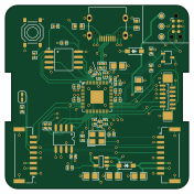
About the Digital clock72 PCB
Digital clock72 is an open source RP2040/RP2350 PCB design by marino222, published on GitHub under the MIT license. It is a 4-layer board measuring 44 × 44 mm, with 46 components from 22 distinct parts.
Its main chip is the RP2040, from the RP2040/RP2350 family. Other key parts include the AP2112K-3.3TRG1, W25Q32JVSSIQ and THVD1450DR. By type, the board carries 20 capacitors, 13 resistors, 4 ICs, 4 connectors, 2 diodes and 1 transistor.
It belongs with the displays & leds designs in this gallery.
From the project
Kinetic Art Clock consisting of LCD displays
Each pixel node is one self contained board carrying one microcontroller and one round LCD, wired to its neighbors over a shared bus. The full array is this same board built N times, with a target of 72 nodes. This README describes one of the nodes.
- An RP2040 microcontroller and an external flash chip - A connector for the GC9A01 round LCD - An RS485 transceiver and two bus connectors so boards can be daisy chained - Power regulation, with separate rails for the logic and the display backlight - USB-C and/or SWD pads for flashing firmware
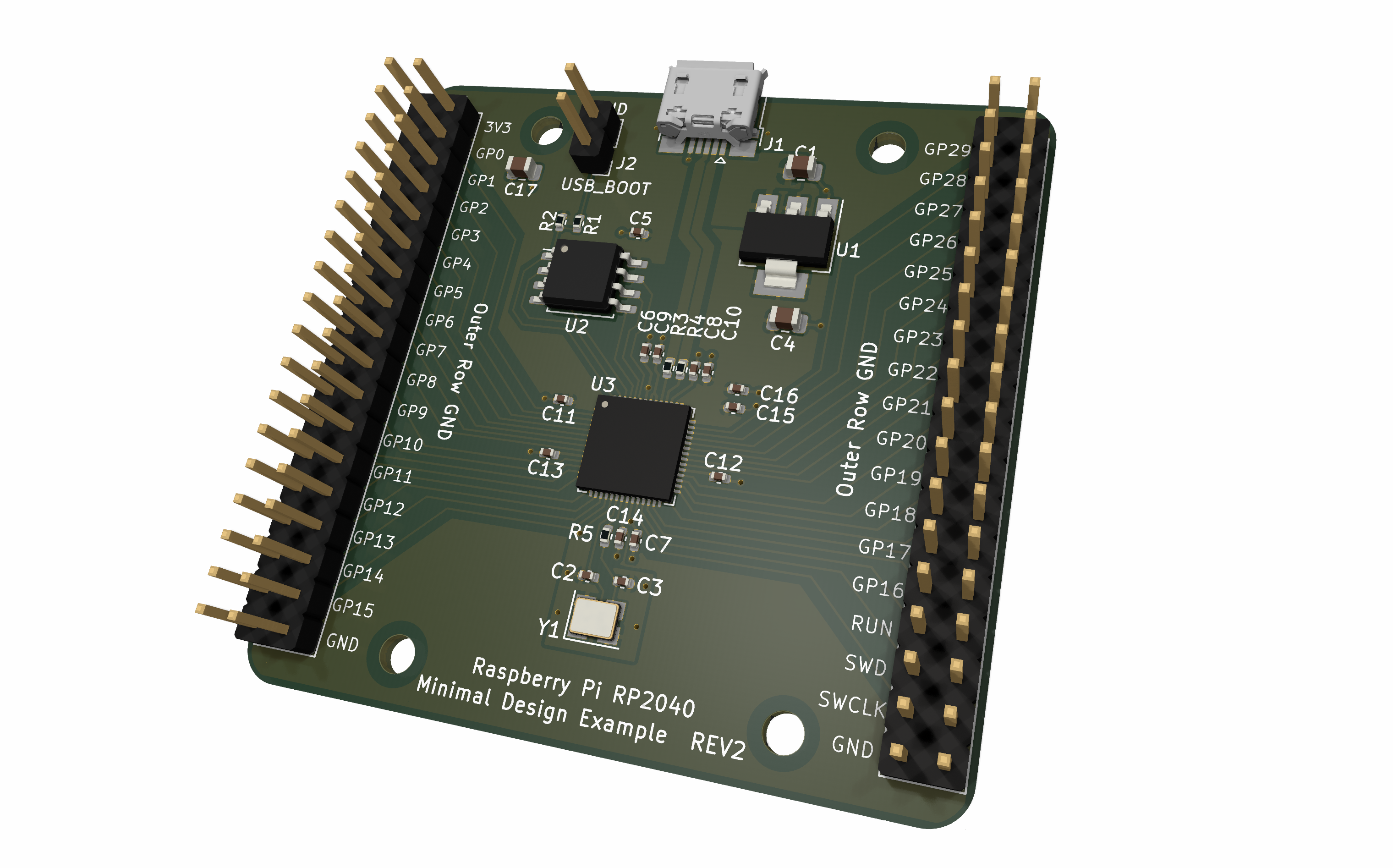
Main components on the Digital clock72
Digital clock72 bill of materials (BOM)
46 components, 22 distinct parts — part numbers from the project's BOM.
| Qty | Part | Footprint | Refs |
|---|---|---|---|
| 1 | AP2112K-3.3TRG1 AP2112K-3.3 Diodes Incorporated | SOT-25-5_L2.9-W1.6-P0.95-LS2.8-BL | U1 |
| 1 | W25Q32JVSSIQ Winbond Elec | SOIC-8_L5.3-W5.3-P1.27-LS8.0-BL | U2 |
| 1 | RP2040 Raspberry Pi | LQFN-56_L7.0-W7.0-P0.4-EP | U3 |
| 1 | THVD1450DR Texas Instruments | SOIC-8_L4.9-W3.9-P1.27-LS6.0-BL | U4 |
| 1 | S8050 J3Y(RANGE:200-350) S8050 Jiangsu Changjing Electronics Technology Co., Ltd. | SOT-23-3_L3.0-W1.7-P0.95-LS2.9-BR | Q1 |
| 1 | ABM8-272-T3 Abracon LLC | CRYSTAL-SMD_4P-L3.2-W2.5-BL | Y1 |
| 1 | TYPE-C-31-M-12 Korean Hroparts Elec | USB-C_SMD-TYPE-C-31-M-12_1 | J1 |
| 2 | BM08B-GHS-TBT(LF)(SN) JST | CONN-SMD_BM08B-GHS-TBT-LF-SN | J2, J3 |
| 1 | AFC11-S12ICA-00 JUSHUO | CONN-SMD-12P_AFC11-S12ICA-00 | J5 |
| 1 | TS-1187A-B-A-B XKB Connection | SW-SMD_4P-L5.1-W5.1-P3.70-LS6.5-TL_H1.5 | SW1 |
| 2 | B5819W SL B5819WSL Jiangsu Changjing Electronics Technology Co., Ltd. | SOD-123_L2.7-W1.6-LS3.7-RD-1 | D1, D2 |
| 11 | CL05B104KO5NNNC 100nF Samsung Electro-Mechanics | C0402 | C1, C2, C3, C4, C5, C6, C7, C8 +3 |
| 4 | GRM21BR61C106KE15L 10uF Murata Electronics | C0805 | C10, C11, C12, C16 |
| 3 | CL05A105KA5NQNC 1uF Samsung Electro-Mechanics | C0402 | C13, C14, C19 |
| 2 | 0402CG150J500NT 15pF FH (Guangdong Fenghua Advanced Tech) | C0402 | C17, C18 |
| 2 | 0603WAF5101T5E 5.1k UNI-ROYAL(Uniroyal Elec) | R0603 | R1, R2 |
| 2 | 0402WGF330JTCE 33 UNI-ROYAL(Uniroyal Elec) | R0402 | R3, R4 |
| 4 | 0402WGF1002TCE 10k UNI-ROYAL(Uniroyal Elec) | R0402 | R5, R9, R10, R13 |
| 2 | 0402WGF1001TCE 1k UNI-ROYAL(Uniroyal Elec) | R0402 | R6, R7 |
| 1 | 0402WGF1200TCE 120 UNI-ROYAL(Uniroyal Elec) | R0402 | R8 |
Show 2 more
| Qty | Part | Footprint | Refs |
|---|---|---|---|
| 1 | 0805W8F470JT5E 47 UNI-ROYAL(Uniroyal Elec) | R0805 | R11 |
| 1 | 0402WGF2201TCE 2.2k UNI-ROYAL(Uniroyal Elec) | R0402 | R12 |
Digital clock72 design files
The KiCad project lives in the marino222/digital-clock72 repository on GitHub; these links point at the commit this page was built from.
Digital clock72: common questions
What microcontroller does the Digital clock72 use?
The Digital clock72 is built around the RP2040, from the RP2040/RP2350 family.
How big is the Digital clock72 PCB?
The Digital clock72 measures 44 × 44 mm, has 4 copper layers and is 1.6062 mm thick.
How many components are on the Digital clock72?
46 components, from 22 distinct parts, with part numbers taken from the project's own BOM. The full bill of materials is listed on this page.
Where can I download the Digital clock72 design files?
From the marino222/digital-clock72 repository on GitHub, which has the KiCad layout, the schematic and the BOM; the links under Design files point to each one.
Can I use the Digital clock72 design in my own project?
Yes, under the terms of its MIT license, which marino222 chose for the repository.
Can I test firmware for the Digital clock72 without the hardware?
Yes. HardLabs builds a simulation of the board from its netlist and BOM, so you can run and debug RP2040/RP2350 firmware against it before you order a PCB.
Similar boards
 RP2040/RP2350
Open Book Abridged Edition
joeycastillo
85 × 115 mm29 parts2LCC-BY-SA-4.08.1k RP2040/RP2350
Corne
foostan
277.2 × 107.5 mm164 parts2LCC-BY-4.07.7k RP2040/RP2350
Corne
277.2 × 107.5 mm164 parts2LCC-BY-4.07.7k RP2040/RP2350
Jitx design
gusmanb
55.5 × 65 mm26 parts4LGPL-3.05.0k RP2040/RP2350
LogicAnalyzer
57 × 55.2 mm6 parts2LGPL-3.05.0k RP2040/RP2350
Main
google
98 × 71 mm102 parts2LApache-2.02.9k