
ELARA antenna amplifier

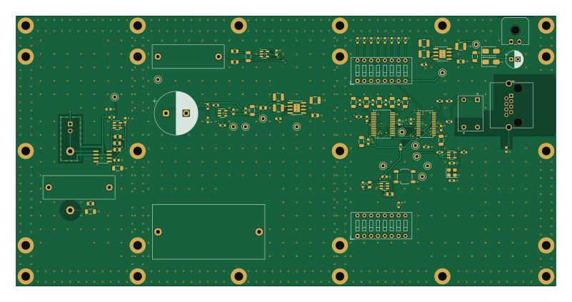
About the ELARA antenna amplifier PCB
ELARA antenna amplifier is an open source PCB design by MatejGomboc, published on GitHub under the CERN-OHL-W-2.0 license. It is a 4-layer board measuring 200 × 100 mm, with 110 components from 61 distinct parts.
Other key parts include the ADM7150ARDZ-5.0-R7, ADM7150ARDZ-3.3-R7, LMP7721MA/NOPB, LMP7715MF/NOPB and OPA388IDBVR. By type, the board carries 45 capacitors, 30 resistors, 14 test points, 9 ICs, 5 connectors and 3 switches.
It belongs with the audio, rf & radio and power & battery designs in this gallery.
From the project
ELF Schumann Resonance Receiver
A professional-grade electric-field receiver for natural ELF radio signals (1--50 Hz), optimised for Schumann resonance monitoring with exceptional sensitivity. Inspired by Renato Romero's electric-field receiver work, engineered for dramatically better noise performance using modern electrometer-grade components.
The system is deliberately simplified: the only custom PCB is the outdoor antenna unit. The indoor side is entirely off-the-shelf.
Main components on the ELARA antenna amplifier
ELARA antenna amplifier bill of materials (BOM)
110 components, 61 distinct parts — part numbers from the project's BOM.
| Qty | Part | Footprint | Refs |
|---|---|---|---|
| 1 | ADM7150ARDZ-5.0-R7 ADM7150ARDZ-5.0 Analog Devices | SOIC-8-1EP_3.9x4.9mm_P1.27mm_EP2.29x3mm | U101 |
| 1 | ADM7150ARDZ-3.3-R7 ADM7150ARDZ-3.3 Analog Devices | SOIC-8-1EP_3.9x4.9mm_P1.27mm_EP2.29x3mm | U102 |
| 1 | LMP7721MA/NOPB LMP7721 Texas Instruments | SOIC-8_3.9x4.9mm_P1.27mm_GuardIsland | U201 |
| 2 | LMP7715MF/NOPB LMP7715 Texas Instruments | SOT-23-5 | U202, U203 |
| 1 | OPA388IDBVR OPA388 Texas Instruments | SOT-23-5 | U301 |
| 1 | PCM1804DB PCM1804 Texas Instruments | SSOP-28_5.3x10.2mm_P0.65mm | U302 |
| 1 | TPS3808G01DBVR TPS3808G01 Texas Instruments | SOT-23-6 | U303 |
| 1 | CS8406-DZZ CS8406 Cirrus Logic | TSSOP-28_4.4x9.7mm_P0.65mm | U401 |
| 1 | SiT2001BI-S2-33E-24.576000 24.576MHz SiTime | SOT-23-5 | Y402 |
| 1 | 43650-0200 DC IN Molex | Molex_Micro-Fit_3.0_43650-0200_1x02_P3.00mm_Horizontal | J101 |
| 1 | PTFE press-fit turret or direct wire FILT_IN - | Turret_PTFE_D3.0mm_Drill1.6mm | J201 |
| 1 | no header: bias resistor leads soldered in the holes BIAS - | PinHeader_1x02_P2.54mm_Vertical_NoSilk | J202 |
| 1 | PTFE press-fit turret or direct wire PLATE_RET - | Turret_PTFE_D3.0mm_Drill1.6mm | J203 |
| 1 | RJHSE-5380 AES3 OUT Amphenol | RJ45_Amphenol_RJHSE5380 | J401 |
| 1 | TL3342F160QG RESET E-Switch | SW_SPST_TL3342 | SW301 |
| 1 | 206-8ST PCM1804 MODE CTS | SW_DIP_SPSTx08_Slide_9.78x22.5mm_W7.62mm_P2.54mm | SW302 |
| 1 | 206-8ST CS8406 MODE CTS | SW_DIP_SPSTx08_Slide_9.78x22.5mm_W7.62mm_P2.54mm | SW401 |
| 1 | 5000 +9V Keystone | TestPoint_Keystone_5000-5004_Miniature | TP101 |
| 1 | 5000 +5VA Keystone | TestPoint_Keystone_5000-5004_Miniature | TP102 |
| 1 | 5000 +5V_PRE Keystone | TestPoint_Keystone_5000-5004_Miniature | TP103 |
Show 41 more
| Qty | Part | Footprint | Refs |
|---|---|---|---|
| 1 | 5000 +3V3 Keystone | TestPoint_Keystone_5000-5004_Miniature | TP104 |
| 1 | 5000 PREAMP_OUT Keystone | TestPoint_Keystone_5000-5004_Miniature | TP201 |
| 1 | 5000 BIAS_BUF Keystone | TestPoint_Keystone_5000-5004_Miniature | TP202 |
| 1 | 5000 GUARD_DRV Keystone | TestPoint_Keystone_5000-5004_Miniature | TP203 |
| 2 | 5001 GND Keystone | TestPoint_Keystone_5000-5004_Miniature | TP204, TP405 |
| 1 | 5000 OVFL Keystone | TestPoint_Keystone_5000-5004_Miniature | TP301 |
| 1 | 5000 MCLK_ADC Keystone | TestPoint_Keystone_5000-5004_Miniature | TP401 |
| 1 | 5000 BCK Keystone | TestPoint_Keystone_5000-5004_Miniature | TP402 |
| 1 | 5000 LRCK Keystone | TestPoint_Keystone_5000-5004_Miniature | TP403 |
| 1 | 5000 RESET_N Keystone | TestPoint_Keystone_5000-5004_Miniature | TP404 |
| 1 | S22083 Newava | Transformer_Newava_S22083 | TR401 |
| 1 | SS34-E3/57T SS34 Vishay | D_SMA | D101 |
| 1 | SMAJ13A Littelfuse | D_SMA | D102 |
| 1 | EEU-FR1E101 100u Panasonic | CP_Radial_D6.3mm_P2.50mm | C101 |
| 7 | GRM31CR71E106KA12L 10u Murata | C_1206_3216Metric | C102, C204, C305, C309, C313, C315, C402 |
| 6 | GRM32ER71E226KE15L 22u Murata | C_1210_3225Metric | C103, C104, C105, C108, C109, C110 |
| 2 | GRM188R71E105KA12D 1u Murata | C_0603_1608Metric | C106, C111 |
| 2 | GRM21BR71E225KA73L 2.2u Murata | C_0805_2012Metric | C107, C112 |
| 1 | GRM31CR61C226ME15L 22u Murata | C_1206_3216Metric | C113 |
| 17 | GRM188R71H104KA93D 100n Murata | C_0603_1608Metric | C114, C203, C206, C208, C304, C306, C308, C310 +9 |
| 1 | GRM2195C1H153JA01D 15n Murata | C_0805_2012Metric | C201 |
| 1 | MKS4C061007G00KSSD 100u WIMA | C_Rect_L41.5mm_W20.0mm_P37.50mm_MKS4 | C202 |
| 1 | GRM1885C1H221JA01D 220p Murata | C_0603_1608Metric | C205 |
| 1 | EEU-FR1C472 4700u Panasonic | CP_Radial_D16.0mm_P7.50mm | C207 |
| 2 | GRM31C5C1H104JA01L 100n Murata | C_1206_3216Metric | C209, C302 |
| 2 | MKS4C051005F00KSSD 10u WIMA | C_Rect_L26.5mm_W8.5mm_P22.50mm_MKS4 | C210, C301 |
| 1 | GRM1885C1H272JA01D 2.7n Murata | C_0603_1608Metric | C303 |
| 1 | ERA-6AEB100V 10 Panasonic | R_0805_2012Metric | R101 |
| 4 | ERA-6AEB104V 100k Panasonic | R_0805_2012Metric | R201, R207, R306, R308 |
| 1 | ERA-6AEB102V 1k Panasonic | R_0805_2012Metric | R202 |
| 1 | ERA-3AEB471V 470 Panasonic | R_0603_1608Metric | R203 |
| 2 | ERA-3VRW4702V 47k Panasonic | R_0603_1608Metric | R204, R205 |
| 1 | ERA-3AEB102V 1k Panasonic | R_0603_1608Metric | R206 |
| 2 | ERA-3AEB103V 10k Panasonic | R_0603_1608Metric | R208, R304 |
| 1 | ERA-6AEB473V 47k Panasonic | R_0805_2012Metric | R301 |
| 1 | ERA-6AEB103V 10k Panasonic | R_0805_2012Metric | R302 |
| 1 | ERA-3AEB101V 100 Panasonic | R_0603_1608Metric | R303 |
| 10 | ERA-3AEB473V 47k Panasonic | R_0603_1608Metric | R305, R403, R404, R405, R406, R407, R408, R409 +2 |
| 1 | ERA-3AEB9531V 9.53k Panasonic | R_0603_1608Metric | R307 |
| 2 | ERA-3AEB330V 33 Panasonic | R_0603_1608Metric | R401, R402 |
| 2 | TNPW060322R0BEEA 22 Vishay Dale | R_0603_1608Metric | R412, R413 |
ELARA antenna amplifier design files
The KiCad project lives in the MatejGomboc/ELF-Schumann-Resonance-Receiver repository on GitHub; these links point at the commit this page was built from.
ELARA antenna amplifier: common questions
How big is the ELARA antenna amplifier PCB?
The ELARA antenna amplifier measures 200 × 100 mm, has 4 copper layers and is 1.6 mm thick.
How many components are on the ELARA antenna amplifier?
110 components, from 61 distinct parts, with part numbers taken from the project's own BOM. The full bill of materials is listed on this page.
Where can I download the ELARA antenna amplifier design files?
From the MatejGomboc/ELF-Schumann-Resonance-Receiver repository on GitHub, which has the KiCad layout, the schematic and the BOM; the links under Design files point to each one.
Can I use the ELARA antenna amplifier design in my own project?
Yes, under the terms of its CERN-OHL-W-2.0 license, which MatejGomboc chose for the repository.
More boards in ELF-Schumann-Resonance-Receiver
Similar boards

EinkPDA screen
TalismanDesign
95 × 54 mm27 parts2LApache-2.02.0k
Stack chan
stack-chan
50 × 50 mm33 parts2LApache-2.01.7k
Display Carrier
AxxAxx
35.6 × 58.2 mm5 parts2LGPL-3.01.7k
KLOR
GEIGEIGEIST
160.2 × 118.3 mm79 parts2LGPL-3.01.2k
ProgrammingAdapter
stuartpittaway
10.5 × 83 mm3 parts2LCC-BY-NC-4.01.1k
TemperaturePCB PANEL
116 × 75.5 mm178 parts2LCC-BY-NC-4.01.1k