
Granola beacon

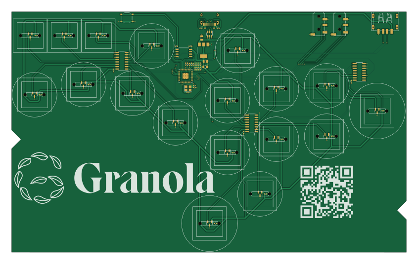
About the Granola beacon PCB
Granola beacon is an open source RP2040/RP2350 PCB design by michaelswitzer, published on GitHub under the CC-BY-NC-4.0 license. It is a 2-layer board measuring 211 × 128.8 mm, with 79 components from 21 distinct parts.
Its main chip is the RP2040, from the RP2040/RP2350 family. Other key parts include the AMS1117-3.3_SOT223, USBLC6-2SC6, W25Q128JVS, 74HC4051 and DRV5053. By type, the board carries 38 capacitors, 25 ICs, 6 resistors, 3 inductors, 2 connectors and 1 crystal.
From the project
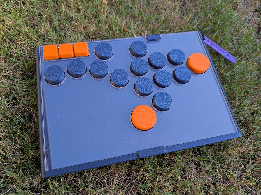
Granola Beacon: arcade controller with hall effect switches
The Beacon is a button box style arcade controller by Granola Arcade. It is designed to use magnetic "hall effect" switches for increased precision.
The .step files for the case is optimized for FDM 3D printers. I recommend PLA with at least 15% infill but you can use any material you wish.
The design for the acrylic top is also included, which you can get fabricated or print a replacement on a 3D printer.
Main components on the Granola beacon
Granola beacon bill of materials (BOM)
79 components, 21 distinct parts — part numbers from the project's BOM.
| Qty | Part | Footprint | Refs |
|---|---|---|---|
| 1 | AMS1117-3.3_SOT223 | SOT-223-3_TabPin2 | U1 |
| 1 | USBLC6-2SC6 | SOT-23-6 | U2 |
| 1 | RP2040 | RP2040-QFN-56 | U3 |
| 1 | W25Q128JVS | SOIC-8_5.23x5.23mm_P1.27mm | U4 |
| 3 | 74HC4051 | SOIC-16_3.9x9.9mm_P1.27mm | U5, U6, U7 |
| 18 | DRV5053 | SOT-23 | U9, U10, U11, U12, U13, U14, U15, U16 +10 |
| 1 | ABLS-12.000MHZ-B4-T | Crystal_SMD_3225-4Pin_3.2x2.5mm | Y1 |
| 2 | AUDIOJACK3 AudioJack3 | Jack_3.5mm_PJ320D_Horizontal | J1, J2 |
| 1 | TS-1187A-B-A-B | SW_Push_1P1T_XKB_TS-1187A | SW1 |
| 1 | HE_Switch | HE_Switch | UP2 |
| 1 | HRO-TYPE-C-31-M-12 | HRO-TYPE-C-31-M-12-Assembly | USB1 |
| 1 | C42591 USB_A | USB-A-SMD_C42591 | USB2 |
| 3 | HE_Switch | HE_Switch | L1, L2, L3 |
| 3 | 10U 10u | C_0805_2012Metric | C1, C2, C3 |
| 31 | 100N 100n | C_0402_1005Metric | C4, C5, C6, C7, C8, C9, C10, C11 +23 |
| 2 | 1u | C_0402_1005Metric | C13, C14 |
| 2 | 27P 27p | C_0402_1005Metric | C16, C17 |
| 2 | 5.1k | R_0402_1005Metric | R1, R2 |
| 1 | HE_Switch | HE_Switch | R3 |
| 1 | 27 | C_0402_1005Metric | R4 |
Show 1 more
| Qty | Part | Footprint | Refs |
|---|---|---|---|
| 2 | 1k | C_0402_1005Metric | R5, R6 |
Granola beacon design files
The KiCad project lives in the michaelswitzer/granola-beacon repository on GitHub; these links point at the commit this page was built from.
Granola beacon: common questions
What microcontroller does the Granola beacon use?
The Granola beacon is built around the RP2040, from the RP2040/RP2350 family.
How big is the Granola beacon PCB?
The Granola beacon measures 211 × 128.8 mm, has 2 copper layers and is 1.6 mm thick.
How many components are on the Granola beacon?
79 components, from 21 distinct parts, with part numbers taken from the project's own BOM. The full bill of materials is listed on this page.
Where can I download the Granola beacon design files?
From the michaelswitzer/granola-beacon repository on GitHub, which has the KiCad layout, the schematic and the BOM; the links under Design files point to each one.
Can I use the Granola beacon design in my own project?
It is published under CC-BY-NC-4.0, which limits how it may be reused; read the license before building on it.
Can I test firmware for the Granola beacon without the hardware?
Yes. HardLabs builds a simulation of the board from its netlist and BOM, so you can run and debug RP2040/RP2350 firmware against it before you order a PCB.
Similar boards
 RP2040/RP2350
Open Book Abridged Edition
joeycastillo
85 × 115 mm29 parts2LCC-BY-SA-4.08.1k RP2040/RP2350
Corne
foostan
277.2 × 107.5 mm164 parts2LCC-BY-4.07.7k RP2040/RP2350
Corne
277.2 × 107.5 mm164 parts2LCC-BY-4.07.7k RP2040/RP2350
LogicAnalyzer
gusmanb
57 × 55.2 mm6 parts2LGPL-3.05.0k RP2040/RP2350
Jitx design
55.5 × 65 mm26 parts4LGPL-3.05.0k RP2040/RP2350
Pro V2
kata0510
290.1 × 130 mm270 parts2LMIT2.3k