
Boulder clock replacent bord

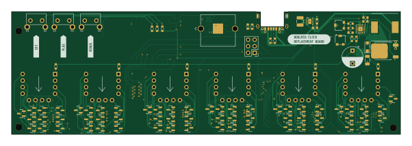
About the Boulder clock replacent bord PCB
Boulder clock replacent bord is an open source ESP8266 PCB design by mickdassive, published on GitHub. It is a 4-layer board measuring 150.3 × 47.5 mm, with 208 components from 38 distinct parts.
Its main chip is the ESP-12F, from the ESP8266 family. Other key parts include the PI4IOE5V6416LEX, PCF8523TK/1,118, CD4028BNSR, HV9150 and TPS63031DSKR. By type, the board carries 88 resistors, 61 transistors, 30 capacitors, 12 ICs, 3 switches and 2 connectors.
It belongs with the iot & wireless designs in this gallery.
From the project
This project provides the source code and design files for the Boulder Clock Replacement Board, designed as a direct drop-in replacement for the original Boulder Clock hardware. The board is fully compatible with existing clock circuitry—no additional wiring or modifications are
This project provides the source code and design files for the Boulder Clock Replacement Board, designed as a direct drop-in replacement for the original Boulder Clock hardware. The board is fully compatible with existing clock circuitry—no additional wiring or modifications are required.
- Drop-in replacement for Boulder Clock boards—no extra wiring needed - Open-source hardware and software design (GPLv3 license) - Improved time accuracy - WiFi configuration via web interface (WiFi Manager) - Adjustable GMT offset, DST settings, and 12/24 hour mode - Easy-to-follow assembly instructions
Main components on the Boulder clock replacent bord
Boulder clock replacent bord bill of materials (BOM)
208 components, 38 distinct parts.
| Qty | Part | Footprint | Refs |
|---|---|---|---|
| 2 | PI4IOE5V6416LEX | TSSOP-24_4.4x7.8mm_P0.65mm | U1, U2 |
| 1 | PCF8523TK/1,118 | HVSON-8-1EP_4x4mm_P0.8mm_EP2.2x3.1mm | U3 |
| 6 | CD4028BNSR | SOP-16_4.4x10.4mm_P1.27mm | U4, U5, U7, U8, U9, U10 |
| 1 | ESP-12F | ESP-12E | U6 |
| 1 | HV9150 | QFN-16-1EP_3x3mm_P0.5mm_EP1.7x1.7mm | U11 |
| 1 | TPS63031DSKR | TPS63031DSKR | U12 |
| 60 | BSS127H6327XTSA2 | SOT-23 | Q1, Q2, Q3, Q4, Q5, Q6, Q7, Q8 +52 |
| 1 | FQD12N20LTM-F085P | TO-252-2 | Q21 |
| 1 | 32KHz768 | XTAL_SC32S-7PF20PPM_EPS | Y1 |
| 1 | PROG_PORT | PinHeader_2x03_P2.54mm_Vertical | J1 |
| 1 | USB4515-GF-A | USB4515-GF-A_GCT | J2 |
| 1 | 36-2997-ND | 2997_KEY | BT1 |
| 1 | SolderJumper_2_Open | SolderJumper-2_P1.3mm_Open_RoundedPad1.0x1.5mm | JP1 |
| 6 | ~ | boulder nixie | NT1, NT2, NT3, NT4, NT5, NT6 |
| 1 | SET | SW_Tactile_SKHH_Angled | SW1 |
| 1 | PLUS | SW_Tactile_SKHH_Angled | SW2 |
| 1 | MINUS | SW_Tactile_SKHH_Angled | SW3 |
| 1 | NHP140SFT3G | NHP140SF-D | D1 |
| 1 | BRL3225T1R5M 1uH5 | L_1210_3225Metric | L1 |
| 1 | NS10145T470MNVV 47uH | L_Taiyo-Yuden_NR-10050_9.8x10.0mm | L2 |
Show 18 more
| Qty | Part | Footprint | Refs |
|---|---|---|---|
| 10 | 10uF | C_0603_1608Metric | C1, C2, C10, C11, C15, C17, C18, C20 +2 |
| 15 | 0uF1 | C_0603_1608Metric | C3, C4, C6, C7, C8, C9, C12, C13 +7 |
| 1 | 22uF | C_0603_1608Metric | C5 |
| 1 | 4uF7 | C_0603_1608Metric | C25 |
| 1 | 1uF | C_0603_1608Metric | C26 |
| 1 | 250BXC22MEFC10X16 22uF | CP_Radial_D8.0mm_P5.00mm | C28 |
| 1 | C1206X104K251T 0uF1 | C_1206_3216Metric | C30 |
| 10 | 10K | R_0603_1608Metric | R1, R2, R4, R5, R6, R7, R8, R11 +2 |
| 2 | 1K | R_0603_1608Metric | R3, R39 |
| 3 | 2K2 | R_0603_1608Metric | R9, R10, R43 |
| 60 | 3K3 | R_0603_1608Metric | R14, R15, R16, R17, R18, R20, R21, R22 +52 |
| 6 | 80K | R_0603_1608Metric | R19, R30, R50, R61, R72, R83 |
| 1 | 330R | R_0603_1608Metric | R36 |
| 2 | 5K1 | R_0603_1608Metric | R37, R38 |
| 1 | PVG3A102C01R00 1K | POT_PVG3A_BRN | R40 |
| 1 | 47K | R_0603_1608Metric | R41 |
| 1 | 1M | R_0603_1608Metric | R42 |
| 1 | PVG3A502C01R00 5K | POT_PVG3A_BRN | R44 |
Boulder clock replacent bord design files
The KiCad project lives in the mickdassive/boulder_clock_replacent_bord repository on GitHub; these links point at the commit this page was built from.
Boulder clock replacent bord: common questions
What microcontroller does the Boulder clock replacent bord use?
The Boulder clock replacent bord is built around the ESP-12F, from the ESP8266 family.
How big is the Boulder clock replacent bord PCB?
The Boulder clock replacent bord measures 150.3 × 47.5 mm, has 4 copper layers and is 1.6062 mm thick.
How many components are on the Boulder clock replacent bord?
208 components, from 38 distinct parts. The full bill of materials is listed on this page.
Where can I download the Boulder clock replacent bord design files?
From the mickdassive/boulder_clock_replacent_bord repository on GitHub, which has the KiCad layout and the schematic; the links under Design files point to each one.
Can I use the Boulder clock replacent bord design in my own project?
The repository has no license, so all rights stay with mickdassive. Use it as a reference, and ask the author before reusing the design.
Can I test firmware for the Boulder clock replacent bord without the hardware?
Yes. HardLabs builds a simulation of the board from its netlist and BOM, so you can run and debug ESP8266 firmware against it before you order a PCB.
Similar boards
 ESP8266
ControllerCircuit
stuartpittaway
75 × 30 mm20 parts2LCC-BY-NC-4.01.1k ESP8266
HASwitchPlate
aderusha
60 × 40 mm8 parts2LMIT738 ESP8266
RatGDO-OpenSource-D1Mini-ESP8266
Kaldek
47.8 × 63.3 mm12 parts2LMIT506 ESP8266
Goatgdo
32.9 × 53.3 mm23 parts2LMIT506 ESP8266
RatGDO-OpenSource-Bare-ESP8266
55 × 82.7 mm20 parts2LMIT506 ESP8266
Iaq board
nkitanov
70.1 × 43.2 mm17 parts2LNo license398