
EEE3088 Power-Subsystem 2025

About the EEE3088 Power-Subsystem 2025 PCB
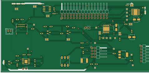
EEE3088 Power-Subsystem 2025 is an open source PCB design by miruokami, published on GitHub. It is a 2-layer board measuring 119.2 × 55 mm, with 70 components from 41 distinct parts.
Other key parts include the DRV8833PWP, TP4056, AMS1117, MP2315 and INA219AxD. By type, the board carries 27 resistors, 14 capacitors, 9 jumpers, 6 ICs, 6 connectors and 3 transistors.
It belongs with the robotics & motion and power & battery designs in this gallery.
From the project
Welcome to the repository for the EEE3088F Micro-Mouse Power Subsystem Project. This project focuses on designing and implementing a compact and efficient power module for a simplified micro-mouse robot. The goal is to meet all electrical and mechanical specifications, stay withi
Welcome to the repository for the EEE3088F Micro-Mouse Power Subsystem Project. This project focuses on designing and implementing a compact and efficient power module for a simplified micro-mouse robot. The goal is to meet all electrical and mechanical specifications, stay within a strict budget, and ensure seamless integration with the larger micro-mouse system.
Main components on the EEE3088 Power-Subsystem 2025
EEE3088 Power-Subsystem 2025 bill of materials (BOM)
70 components, 41 distinct parts.
| Qty | Part | Footprint | Refs |
|---|---|---|---|
| 2 | DRV8833PWP | HTSSOP-16-1EP_4.4x5mm_P0.65mm_EP3.4x5mm_Mask2.46x2.31mm_ThermalVias | U1, U5 |
| 1 | TP4056 | SOIC-8-1EP_3.9x4.9mm_P1.27mm_EP2.29x3mm | U2 |
| 1 | AMS1117 | SOT-223-3_TabPin2 | U3 |
| 1 | MP2315 MP2315GJ | PinHeader_2x04_P2.54mm_Horizontal | U4 |
| 1 | INA219AxD | SOIC-8_3.9x4.9mm_P1.27mm | U6 |
| 3 | IRLML6402 | SOT-23 | Q1, Q2, Q3 |
| 1 | USB_C_Receptacle | USB_C_Receptacle_Amphenol_12401610E4-2A | J1 |
| 1 | Battery | JST_PH_B2B-PH-K_1x02_P2.00mm_Vertical | J2 |
| 2 | Conn_01x02_Pin | PinHeader_1x02_P2.54mm_Vertical | J3, J7 |
| 1 | Conn_02x16_Odd_Even | PinHeader_2x16_P2.54mm_Horizontal | J4 |
| 1 | B6B-PH-K-S_LF__SN_ | PinHeader_1x06_P2.54mm_Horizontal | J5 |
| 9 | SolderJumper_2_Open | SolderJumper-2_P1.3mm_Open_Pad1.0x1.5mm | JP1, JP2, JP3, JP4, JP5, JP6, JP7, JP8 +1 |
| 1 | SW_Push | Nidec_Copal_SH-7010A | SW1 |
| 2 | LED | LED_0201_0603Metric | GREEN1, RED1 |
| 1 | D_Schottky | D_2114_3652Metric | D9 |
| 1 | 4.7u | L_0201_0603Metric | L1 |
| 2 | 10u | C_0603_1608Metric | C1, C7 |
| 2 | 2.2uF | C_0603_1608Metric | C2, C12 |
| 1 | 100nF | C_0603_1608Metric | C3 |
| 2 | 10uF | C_0603_1608Metric | C4, C13 |
Show 21 more
| Qty | Part | Footprint | Refs |
|---|---|---|---|
| 1 | 10uF | CP_Elec_4x3 | C5 |
| 2 | 0.01uF | CP_Elec_4x3 | C6, C11 |
| 1 | 22u | C_0603_1608Metric | C8 |
| 2 | 1u | C_0603_1608Metric | C9, C10 |
| 1 | 0.1u | C_0603_1608Metric | C14 |
| 1 | 1.2k | R_0603_1608Metric | R1 |
| 1 | 220 | R_0603_1608Metric | R2 |
| 1 | 5.6k | R_0603_1608Metric | R3 |
| 1 | 0.4 | R_0603_1608Metric | R4 |
| 5 | 1k | R_0603_1608Metric | R5, R6, R16, R24, R27 |
| 2 | 1 | R_0603_1608Metric | R7, R18 |
| 2 | 0.39 | R_0603_1608Metric | R8, R19 |
| 1 | 33 | R_0603_1608Metric | R9 |
| 2 | 100k | R_0603_1608Metric | R10, R15 |
| 1 | 33k | R_0603_1608Metric | R11 |
| 1 | 1M | R_0603_1608Metric | R12 |
| 2 | 5.1k | R_0603_1608Metric | R13, R14 |
| 3 | 10K | R_0603_1608Metric | R17, R21, R26 |
| 1 | 3.3k | R_0603_1608Metric | R20 |
| 1 | 10 | R_0603_1608Metric | R22 |
| 2 | R_LIMIT | R_0603_1608Metric | R23, R25 |
EEE3088 Power-Subsystem 2025 design files
The KiCad project lives in the miruokami/EEE3088_Power-Subsystem_2025 repository on GitHub; these links point at the commit this page was built from.
EEE3088 Power-Subsystem 2025: common questions
How big is the EEE3088 Power-Subsystem 2025 PCB?
The EEE3088 Power-Subsystem 2025 measures 119.2 × 55 mm, has 2 copper layers and is 1.6 mm thick.
How many components are on the EEE3088 Power-Subsystem 2025?
70 components, from 41 distinct parts. The full bill of materials is listed on this page.
Where can I download the EEE3088 Power-Subsystem 2025 design files?
From the miruokami/EEE3088_Power-Subsystem_2025 repository on GitHub, which has the KiCad layout and the schematic; the links under Design files point to each one.
Can I use the EEE3088 Power-Subsystem 2025 design in my own project?
The repository has no license, so all rights stay with miruokami. Use it as a reference, and ask the author before reusing the design.
Similar boards
EinkPDA screen
TalismanDesign
95 × 54 mm27 parts2LApache-2.02.0k
Stack chan
stack-chan
50 × 50 mm33 parts2LApache-2.01.7k
Display Carrier
AxxAxx
35.6 × 58.2 mm5 parts2LGPL-3.01.7k
Module 16S PassiveBalanceAddOn
stuartpittaway
61 × 74 mm86 parts2LCC-BY-NC-4.01.1k
TemperaturePCB PANEL
116 × 75.5 mm178 parts2LCC-BY-NC-4.01.1k
ProgrammingAdapter
10.5 × 83 mm3 parts2LCC-BY-NC-4.01.1k