
Clock

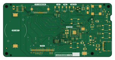
About the Clock PCB
Clock is an open source RP2040/RP2350 PCB design by MitchellStride, published on GitHub. It is a 2-layer board measuring 100 × 50 mm, with 94 components from 41 distinct parts.
Its main chip is the RP2040, from the RP2040/RP2350 family. Other key parts include the SRV05-4, RT9080-33GJ5, W25Q64JV and DS1307Z+. By type, the board carries 33 capacitors, 30 resistors, 6 connectors, 6 diodes, 5 ICs and 5 switches.
It belongs with the displays & leds designs in this gallery.
From the project
RP2040 RTC Module, highly compatible with JLCPCB's basic SMT components.
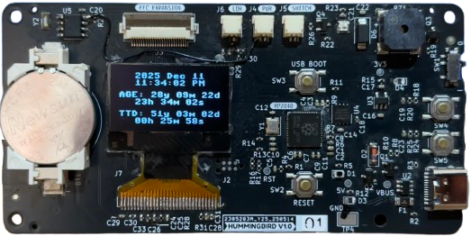
The Hummingbird RP2040 Clock Module is designed for crafting artisan clocks by pairing it with different clock faces. Its modular design allows this project to be shared across various display technologies.
The test OLED above shows time, my age, and my time to death countdown based on my life expectancy.
- Life Clock: A countdown to estimated time of death using seven-segment displays - Nixie Clock: A personal take on the classic Nixie tube clock, featuring IN-12 tubes - 0402 Year Calendar Inspired by the Yetch THE EVERY DAY GOAL CALENDAR
Main components on the Clock
Clock bill of materials (BOM)
94 components, 41 distinct parts — part numbers from the project's BOM.
| Qty | Part | Footprint | Refs |
|---|---|---|---|
| 1 | RP2040 | QFN-56_EP_7x7_Pitch0.4mm | U1 |
| 1 | SRV05-4 | SOT-23-6 | U2 |
| 1 | RT9080-33GJ5 | SOT-23-5 | U3 |
| 1 | W25Q64JV | WSON-8-1EP_4x4mm_P0.8mm_EP2.2x3mm | U4 |
| 1 | DS1307Z+ | SOIC-8_3.9x4.9mm_P1.27mm | U5 |
| 2 | AO3401A | SOT-23 | Q1, Q2 |
| 1 | AO3400A | SOT-23 | Q3 |
| 1 | 2N7002 | SOT-23 | Q4 |
| 1 | XYDBPCNANF-12MHZ | Crystal_SMD_3225-4Pin_3.2x2.5mm | Y1 |
| 1 | 32.768KHZ 32.768kHz | Crystal_SMD_3215-2Pin_3.2x1.5mm | Y2 |
| 1 | USB_C_RECEPTACLE_USB2.0 USB_C_Receptacle_USB2.0 | USB-C-16p | J1 |
| 1 | C202112 FFC 24 | Hirose_FH12-24S-0.5SH_1x24-1MP_P0.50mm_Horizontal | J3 |
| 3 | C160402 5V | JST_SH_SM02B-SRSS-TB_1x02-1MP_P1.00mm_Horizontal | J4, J5, J6 |
| 1 | OLED | OLED-128O064D_edit_reverse_v2 | J7 |
| 1 | CR2032 | Q&J_CR2032-BS-6-1 | BT1 |
| 1 | CMT-8504-100-SMT-TR | MagneticBuzzer_CUI_CMT-8504-100-SMT | BZ1 |
| 1 | C516068 12V 3A | Fuse_1206_3216Metric | F1 |
| 1 | SSSS811101 | SSSS811101 | SW1 |
| 4 | TS-1187A-B-A-B | SW_SPST_TL3342_RT | SW2, SW3, SW4, SW5 |
| 1 | C2296 LED_Y | LED_0805_2012Metric | D1 |
Show 21 more
| Qty | Part | Footprint | Refs |
|---|---|---|---|
| 1 | 5.6V | D_MiniMELF | D2 |
| 2 | C2297 LED_G | LED_0805_2012Metric | D3, D4 |
| 1 | WS2812B-2020 | WS2812B-2020 | D5 |
| 1 | SS14 | D_SMA | D6 |
| 2 | 10U 10u | C_0402_1005Metric | C1, C22 |
| 11 | 1u | C_0402_1005Metric | C2, C8, C18, C20, C21, C24, C26, C27 +3 |
| 14 | 0.1U 0.1u | C_0402_1005Metric | C3, C4, C5, C6, C7, C9, C10, C11 +6 |
| 2 | 10P 10p | C_0402_1005Metric | C12, C13 |
| 3 | 4.7U 4.7u | C_0402_1005Metric | C16, C17, C31 |
| 1 | 2.2U 2.2u | C_0402_1005Metric | C28 |
| 6 | 1k | R_0402_1005Metric | R1, R11, R18, R19, R24, R30 |
| 2 | 5.1K 5.1k | R_0402_1005Metric | R2, R3 |
| 9 | 10K 10k | R_0402_1005Metric | R4, R9, R20, R23, R25, R26, R27, R28 +1 |
| 1 | 2.2K 2.2k | R_0402_1005Metric | R5 |
| 2 | 22 | R_0402_1005Metric | R6, R7 |
| 2 | 100K 100k | R_0402_1005Metric | R8, R10 |
| 3 | 4.7K 4.7k | R_0402_1005Metric | R13, R14, R21 |
| 1 | 300 1k | R_0402_1005Metric | R15 |
| 2 | 0 | R_0402_1005Metric_3pad | R16, R17 |
| 1 | 51 | R_0402_1005Metric | R22 |
| 1 | 330K 330k | R_0402_1005Metric | R31 |
Clock design files
The KiCad project lives in the MitchellStride/Hummingbird-RP2040-Clock-Module repository on GitHub; these links point at the commit this page was built from.
Clock: common questions
What microcontroller does the Clock use?
The Clock is built around the RP2040, from the RP2040/RP2350 family.
How big is the Clock PCB?
The Clock measures 100 × 50 mm, has 2 copper layers and is 1.6 mm thick.
How many components are on the Clock?
94 components, from 41 distinct parts, with part numbers taken from the project's own BOM. The full bill of materials is listed on this page.
Where can I download the Clock design files?
From the MitchellStride/Hummingbird-RP2040-Clock-Module repository on GitHub, which has the KiCad layout, the schematic and the BOM; the links under Design files point to each one.
Can I use the Clock design in my own project?
The repository has no license, so all rights stay with MitchellStride. Use it as a reference, and ask the author before reusing the design.
Can I test firmware for the Clock without the hardware?
Yes. HardLabs builds a simulation of the board from its netlist and BOM, so you can run and debug RP2040/RP2350 firmware against it before you order a PCB.
More boards in Hummingbird-RP2040-Clock-Module
Similar boards
 RP2040/RP2350
Open Book Abridged Edition
joeycastillo
85 × 115 mm29 parts2LCC-BY-SA-4.08.1k RP2040/RP2350
Corne
foostan
277.2 × 107.5 mm164 parts2LCC-BY-4.07.7k RP2040/RP2350
Corne
277.2 × 107.5 mm164 parts2LCC-BY-4.07.7k RP2040/RP2350
LogicAnalyzer
gusmanb
57 × 55.2 mm6 parts2LGPL-3.05.0k RP2040/RP2350
Jitx design
55.5 × 65 mm26 parts4LGPL-3.05.0k RP2040/RP2350
Pro V2
kata0510
290.1 × 130 mm270 parts2LMIT2.3k