
Led ir driver

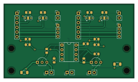
About the Led ir driver PCB
Led ir driver is an open source PCB design by nguyenhuy0426, published on GitHub under the MIT license. It is a 2-layer board measuring 70 × 40 mm, with 36 components from 23 distinct parts.
Other key parts include the LM358P / DIP8 socket. By type, the board carries 12 resistors, 9 connectors, 4 jumpers, 4 capacitors, 2 transistors and 1 IC.
It belongs with the audio and test & measurement designs in this gallery.
From the project
The PPG Signal Simulator is a portable device that generates synthetic PPG (photoplethysmography) waveforms with physiologically accurate morphology. It outputs the signal via a 12‑bit DAC for connection to patient monitors, oscilloscopes, or data acquisition systems.
Mở ledirdriver.kicadpro bằng KiCad 10. Board hai lớp, 70 × 40 mm, FR4 1,6 mm; socket module, socket IC và header xuyên lỗ; toàn bộ điện trở và tụ điện là linh kiện dán. Thư viện symbol, footprint, mô hình 3D đi kèm trong thư mục dự án. Schematic v2.0 dùng dây nối trực tiếp cho từng kênh; mỗi module MCP4725 có cổng I²C riêng (J8 cho IR, J9 cho RED) qua điện trở 100 Ω hoặc jumper bỏ qua. Đọc ELECTRICALAUDIT.md để xem kết quả rà soát điện, cấu hình ADDR và các điều kiện trước khi cấp nguồn. Đọc COMPONENTRATIONALE.md để hiểu lựa chọn linh kiện và PINMAP.md để tra chân nối…
Main components on the Led ir driver
Led ir driver bill of materials (BOM)
36 components, 23 distinct parts — part numbers from the project's BOM.
| Qty | Part | Footprint | Refs |
|---|---|---|---|
| 1 | LM358P / DIP8 socket | DIP8 | U1 |
| 2 | 2N4401 / E-B-C | NPN | Q1, Q2 |
| 1 | MCP4725 IR 0x60 | Socket6 | J1 |
| 1 | IR DAC OUT / GND | Header2 | J2 |
| 1 | MCP4725 RED 0x61 | Socket6 | J3 |
| 1 | RED DAC OUT / GND | Header2 | J4 |
| 1 | IR LED A / K | Header2 | J5 |
| 1 | RED LED A / K | Header2 | J6 |
| 1 | 5V INPUT / GND | Header2 | J7 |
| 1 | I2C IR: SCL SDA 3V3 GND | Header4 | J8 |
| 1 | I2C RED: SCL SDA 3V3 GND | Header4 | J9 |
| 4 | M3 / 3.2mm | Hole | H1, H2, H3, H4 |
| 1 | SCL IR 1-2 BYP / 2-3 100R | SJ3 | JP1 |
| 1 | SDA IR 1-2 BYP / 2-3 100R | SJ3 | JP2 |
| 1 | SCL RED 1-2 BYP / 2-3 100R | SJ3 | JP3 |
| 1 | SDA RED 1-2 BYP / 2-3 100R | SJ3 | JP4 |
| 2 | DNP loop comp | C | C2, C4 |
| 1 | 100nF X7R 50V | C | C5 |
| 1 | 10uF 16V | CP | C7 |
| 4 | 10k 1% | R | R1, R2, R6, R7 |
Show 3 more
| Qty | Part | Footprint | Refs |
|---|---|---|---|
| 2 | 1k | R | R3, R8 |
| 2 | 100R 1% 0.25W | RSense | R4, R9 |
| 4 | 100R 1% | R | R11, R12, R13, R14 |
Led ir driver design files
The KiCad project lives in the nguyenhuy0426/PPG_simulator repository on GitHub; these links point at the commit this page was built from.
Led ir driver: common questions
How big is the Led ir driver PCB?
The Led ir driver measures 70 × 40 mm, has 2 copper layers and is 1.6 mm thick.
How many components are on the Led ir driver?
36 components, from 23 distinct parts, with part numbers taken from the project's own BOM. The full bill of materials is listed on this page.
Where can I download the Led ir driver design files?
From the nguyenhuy0426/PPG_simulator repository on GitHub, which has the KiCad layout, the schematic and the BOM; the links under Design files point to each one.
Can I use the Led ir driver design in my own project?
Yes, under the terms of its MIT license, which nguyenhuy0426 chose for the repository.
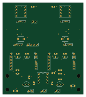
More boards in PPG_simulator
Similar boards
StackLink
gusmanb
52.3 × 10.5 mm5 parts2LGPL-3.05.0k
LevelShifter
28.3 × 39.8 mm21 parts2LGPL-3.05.0k
AnalyzerBoxPCB fork
52.7 × 47.9 mm54 parts4LGPL-3.05.0k
KLOR
GEIGEIGEIST
160.2 × 118.3 mm79 parts2LGPL-3.01.2k
USB
shanteacontrols
52 × 12.6 mm6 parts2LApache-2.0956
Pots
390 × 93 mm75 parts2LApache-2.0956