
Valve driver

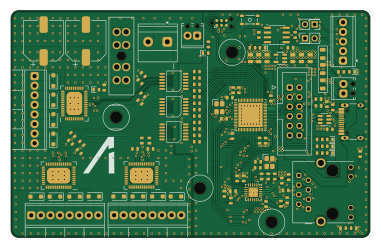
About the Valve driver PCB
Valve driver is an open source STM32 PCB design by npgo22, published on GitHub. It is a 4-layer board measuring 95 × 60 mm, with 142 components from 39 distinct parts.
Its main chip is the STM32H563RIVx, from the STM32 family. Other key parts include the USBLC6-2SC6, AP2112K-3.3, TCAN1462V, LAN8742A and PC817. By type, the board carries 59 resistors, 30 capacitors, 19 diodes, 15 ICs, 12 connectors and 4 fuses.
From the project
4-layer PCB. Controls pneumatic solenoid valves for the APRL bipropellant engine.
4-layer PCB. Controls pneumatic solenoid valves for the APRL bipropellant engine.
STM32H563RIV6 - Cortex-M33, 250 MHz, 2 MB flash, 640 KB SRAM, VFQFPN68 package. Peripherals in use: ETH, FDCAN1, I2C3, USB.
The IPS4140HQ provides per-channel overcurrent, overtemperature, and open-load detection. Its fault status pins are not read by the FSM - they are forwarded to telemetry only. See crates/valve-fsm for the FSM design rationale.
Main components on the Valve driver
Valve driver bill of materials (BOM)
142 components, 39 distinct parts.
| Qty | Part | Footprint | Refs |
|---|---|---|---|
| 1 | USBLC6-2SC6 | SOT-23-6 | U1 |
| 1 | STM32H563RIVx | QFN-68-1EP_8x8mm_P0.4mm_EP6.4x6.4mm | U2 |
| 1 | AP2112K-3.3 | SOT-23-5 | U3 |
| 1 | TCAN1462V | SOIC-8_3.9x4.9mm_P1.27mm | U4 |
| 1 | LAN8742A | VQFN-24-1EP_4x4mm_P0.5mm_EP2.5x2.5mm_ThermalVias | U5 |
| 1 | PC817 | DIP-4_W7.62mm_SMDSocket_SmallPads | U6 |
| 3 | IPS4140HQ | QFN-48_EP_9.01x7.01_Pitch0.5mm | U7, U10, U13 |
| 6 | PS2841-4B | SOIC-12 | U8, U9, U11, U12, U14, U15 |
| 2 | 25 MHz | 3225-4P-L | Y1, Y2 |
| 1 | USB_C_Receptacle_USB2.0_16P | USB_C_Receptacle_HRO_TYPE-C-31-M-12 | J2 |
| 1 | Conn_02x06_Top_Bottom | IDC-Header_2x06_P2.54mm_Vertical | J3 |
| 2 | Screw_Terminal_01x02 | TerminalBlock_Phoenix_MPT-0,5-2-2.54_1x02_P2.54mm_Horizontal | J4, J10 |
| 2 | Conn_02x01 | PinHeader_2x01_P2.54mm_Vertical | J5, J6 |
| 1 | Screw_Terminal_01x05 | TerminalBlock_Phoenix_MPT-0,5-5-2.54_1x05_P2.54mm_Horizontal | J7 |
| 1 | RJ45_Hanrun_HR911105A_Horizontal | RJ45_Hanrun_HR911105A_Horizontal | J8 |
| 1 | Screw_Terminal_01x02 | TerminalBlock_Phoenix_MKDS-1,5-2-5.08_1x02_P5.08mm_Horizontal | J9 |
| 3 | Screw_Terminal_01x08 | TerminalBlock_Phoenix_MPT-0,5-8-2.54_1x08_P2.54mm_Horizontal | J11, J12, J13 |
| 3 | 500mA | Fuse_0805_2012Metric | F1, F2, F3 |
| 1 | 10A hold | FuseHolder_Blade_ATO_Littelfuse_FLR_178.6165 | F4 |
| 1 | SKRPANE010 | SKRPANE010 | SW1 |
Show 19 more
| Qty | Part | Footprint | Refs |
|---|---|---|---|
| 7 | LED | LED_0603 | D1, D2, D3, D4, D5, D6, D7 |
| 12 | SMF4L33CA | D_SOD-123F | D8, D9, D10, D11, D12, D13, D14, D15 +4 |
| 12 | 100nF | C_0603 | C1, C2, C3, C4, C5, C6, C7, C19 +4 |
| 4 | 10pF | C_0603 | C8, C9, C27, C28 |
| 2 | 2.2uF | C_0603 | C10, C11 |
| 6 | 22uF | C_0805 | C12, C13, C14, C15, C16, C17 |
| 2 | 1uF | C_0603 | C18, C23 |
| 1 | 470pF | C_0603 | C24 |
| 1 | 220nF | C_0603 | C26 |
| 2 | 82uF | Yageo Polymer MS | C29, C30 |
| 2 | 4.7k | R_0603 | R1, R2 |
| 34 | 10k | R_0603 | R3, R4, R5, R6, R7, R14, R16, R21 +26 |
| 1 | 120R | R_0603 | R8 |
| 1 | 1.5k | R_0603 | R9 |
| 4 | 47R | R_0603 | R10, R11, R12, R13 |
| 1 | 12.1k | R_0603 | R15 |
| 2 | 330R | R_0603 | R17, R18 |
| 2 | 150k | R_0603 | R19, R20 |
| 12 | 1k | R_0603 | R24, R25, R30, R31, R36, R37, R42, R43 +4 |
Valve driver design files
The KiCad project lives in the npgo22/ALI2Proposal repository on GitHub; these links point at the commit this page was built from.
Valve driver: common questions
What microcontroller does the Valve driver use?
The Valve driver is built around the STM32H563RIVx, from the STM32 family.
How big is the Valve driver PCB?
The Valve driver measures 95 × 60 mm, has 4 copper layers and is 1.6 mm thick.
How many components are on the Valve driver?
142 components, from 39 distinct parts. The full bill of materials is listed on this page.
Where can I download the Valve driver design files?
From the npgo22/ALI2Proposal repository on GitHub, which has the KiCad layout and the schematic; the links under Design files point to each one.
Can I use the Valve driver design in my own project?
The repository has no license, so all rights stay with npgo22. Use it as a reference, and ask the author before reusing the design.
Can I test firmware for the Valve driver without the hardware?
Yes. HardLabs builds a simulation of the board from its netlist and BOM, so you can run and debug STM32 firmware against it before you order a PCB.
More boards in ALI2Proposal
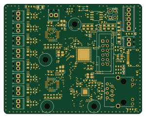 STM32
Pressure
75 × 60 mm139 parts4LNo license0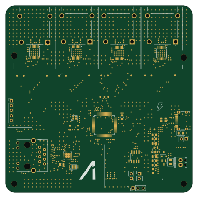 STM32
Thermocouple Board
97 × 97 mm117 parts4LNo license0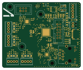 STM32
LC DAQ
71.6 × 60 mm112 parts4LNo license0 STM32
PT
67 × 68 mm105 parts4LNo license0 STM32
TC DAQ
86 × 60 mm99 parts4LNo license0 STM32
Chickenstick
42 × 100 mm96 parts4LNo license0
GPS Module
43 × 34 mm24 parts4LNo license0
Similar boards
 STM32
LumenPnP Motherboard
opulo-inc
149 × 95 mm296 parts4LCC-BY-SA-4.03.7k STM32
Type g
google
169 × 30 mm24 parts2LApache-2.02.9k STM32
Main panel
234 × 84 mm26 parts4LApache-2.02.9k STM32
Base
52.3 × 52.3 mm36 parts2LApache-2.02.9k STM32
Type a
150 × 30 mm14 parts2LApache-2.02.9k STM32
Type c
188 × 30 mm17 parts2LApache-2.02.9k