
Testing hardware

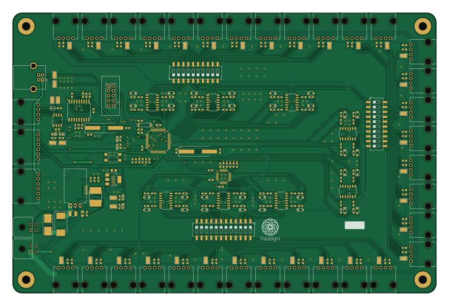
About the Testing hardware PCB
Testing hardware is an open source Microchip SAM PCB design by ParadigmHyperloop, published on GitHub under the Custom license license. It is a 2-layer board measuring 220 × 145.5 mm, with 336 components from 89 distinct parts.
Its main chip is the ATSAMD21J18A-AU, from the Microchip SAM family. Other key parts include the MCP2515-XSO, SN65HVD232, AZ1117IH-3.3TRG1, LM2902 and V7805-2000R. By type, the board carries 123 resistors, 71 capacitors, 40 test points, 39 connectors, 39 diodes and 14 ICs.
From the project
PCBs and other electrical things for Paradigm's post-competition 4 testing efforts
All schematics and layouts in KiCad, plus some simulations https://paradigmhyperloop.com
In summary, (you still need to read the whole thing), these boards are for Paradigm, and Paradigm only. It is shared with the world for the benefit of observers and potential Paradigm team members. If you wish to utilize these designs in any way, you must contact us first and receive written permission to utilize the designs for the purpose you require.
Main components on the Testing hardware
Testing hardware bill of materials (BOM)
336 components, 89 distinct parts — part numbers from the project's BOM.
| Qty | Part | Footprint | Refs |
|---|---|---|---|
| 1 | MCP2515-XSO MCP2515-xSO | SOIC-18W_7.5x11.6mm_P1.27mm | U1 |
| 1 | SN65HVD232 | SOIC-8_3.9x4.9mm_P1.27mm | U2 |
| 1 | AZ1117IH-3.3TRG1 AZ1117-3.3 | SOT-223-3_TabPin2 | U3 |
| 1 | ATSAMD21J18A-AU | TQFP-64_10x10mm_P0.5mm | U4 |
| 1 | LM2902 | SOIC-14_3.9x8.7mm_P1.27mm | U5 |
| 7 | LM2902 | SOIC-14_3.9x8.7mm_P1.27mm | U6, U7, U8, U9, U10, U11, U12 |
| 1 | V7805-2000R | Converter_DCDC_RECOM_R-78HB-0.5L_THT | U13 |
| 1 | ADS114S08BIPBSR | LQFP-32_5x5mm_P0.5mm | U26 |
| 1 | ABLS2-8.000MHZ-D4Y-T 8MHz | Crystal_SMD_HC49-SD_HandSoldering | Y1 |
| 1 | ABLS2-30.000MHZ-D4YF-T 30MHz | Crystal_SMD_HC49-SD_HandSoldering | Y2 |
| 1 | 32.768KHZ 32.768kHz | Crystal_Epson_MC-146 | Y3 |
| 1 | 430450400 POWER | Molex_Micro-Fit_3.0_43045-0400_2x02_P3.00mm_Horizontal | J1 |
| 1 | 705510038 CAN | Connector_Molex_SL_4POS_0705510038 | J2 |
| 1 | 705510038 5V_12_1 | Connector_Molex_SL_4POS_0705510038 | J3 |
| 1 | 705510038 5V_12_2 | Connector_Molex_SL_4POS_0705510038 | J4 |
| 1 | 705510038 5V_12_3 | Connector_Molex_SL_4POS_0705510038 | J5 |
| 1 | 705510038 5V_12_4 | Connector_Molex_SL_4POS_0705510038 | J6 |
| 1 | 705510038 5V_12_5 | Connector_Molex_SL_4POS_0705510038 | J7 |
| 1 | 705510038 5V_12_6 | Connector_Molex_SL_4POS_0705510038 | J8 |
| 1 | 705510038 5V_12_7 | Connector_Molex_SL_4POS_0705510038 | J9 |
Show 69 more
| Qty | Part | Footprint | Refs |
|---|---|---|---|
| 1 | 705510038 5V_12_8 | Connector_Molex_SL_4POS_0705510038 | J10 |
| 1 | 705510038 5V_12_9 | Connector_Molex_SL_4POS_0705510038 | J11 |
| 1 | 705510038 5V_12_10 | Connector_Molex_SL_4POS_0705510038 | J12 |
| 1 | 705510038 5V_12_11 | Connector_Molex_SL_4POS_0705510038 | J13 |
| 1 | 705510038 5V_12_12 | Connector_Molex_SL_4POS_0705510038 | J14 |
| 1 | 705510038 5V_12_13 | Connector_Molex_SL_4POS_0705510038 | J15 |
| 1 | 705510038 5V_12_14 | Connector_Molex_SL_4POS_0705510038 | J16 |
| 1 | 705510038 10V_12_1 | Connector_Molex_SL_4POS_0705510038 | J17 |
| 1 | 705510038 10V_12_2 | Connector_Molex_SL_4POS_0705510038 | J18 |
| 1 | 705510038 10V_12_3 | Connector_Molex_SL_4POS_0705510038 | J19 |
| 1 | 705510038 10V_12_4 | Connector_Molex_SL_4POS_0705510038 | J20 |
| 1 | 705510038 10V_12_5 | Connector_Molex_SL_4POS_0705510038 | J21 |
| 1 | 705510038 10V_12_6 | Connector_Molex_SL_4POS_0705510038 | J22 |
| 1 | POWER_OUT | Molex_Micro-Fit_3.0_43045-0400_2x02_P3.00mm_Horizontal | J23 |
| 1 | 705510038 5V_16_1 | Connector_Molex_SL_4POS_0705510038 | J24 |
| 1 | 705510038 5V_16_2 | Connector_Molex_SL_4POS_0705510038 | J25 |
| 1 | 705510038 5V_16_3 | Connector_Molex_SL_4POS_0705510038 | J26 |
| 1 | 705510038 5V_16_4 | Connector_Molex_SL_4POS_0705510038 | J27 |
| 1 | 705510038 10V_16_1 | Connector_Molex_SL_4POS_0705510038 | J28 |
| 1 | 705510038 10V_16_2 | Connector_Molex_SL_4POS_0705510038 | J29 |
| 1 | 705510038 10V_16_3 | Connector_Molex_SL_4POS_0705510038 | J30 |
| 1 | 705510038 10V_16_4 | Connector_Molex_SL_4POS_0705510038 | J31 |
| 1 | 705510038 5V_16_5 | Connector_Molex_SL_4POS_0705510038 | J32 |
| 1 | 705510038 5V_16_6 | Connector_Molex_SL_4POS_0705510038 | J33 |
| 1 | 705510038 5V_16_7 | Connector_Molex_SL_4POS_0705510038 | J34 |
| 1 | 705510038 5V_16_8 | Connector_Molex_SL_4POS_0705510038 | J35 |
| 1 | 5103308-1 SWD | Connector_TE_5103308-1 | J36 |
| 1 | 705510005 GPIO | Connector_Molex_SL_6POS_0705510005 | J37 |
| 1 | UJ2-BH-1-TH USB_B | USB_B_OST_USB-B1HSxx_Horizontal | J38 |
| 1 | 705510005 ESERCOM | Connector_Molex_SL_6POS_0705510005 | J39 |
| 1 | 0154003.DR 3A | Fuse_Littelfuse_0154003.DR | F1 |
| 1 | DS04-254-2-10BK-SMT INPUT_RANGE_SEL_1 | SW_DIP_SPSTx10_Slide_6.7x26.96mm_W8.61mm_P2.54mm_LowProfile | SW1 |
| 1 | DS04-254-2-10BK-SMT INPUT_RANGE_SEL_2 | SW_DIP_SPSTx10_Slide_6.7x26.96mm_W8.61mm_P2.54mm_LowProfile | SW2 |
| 1 | TL3305AF160QG RESET | SW_SPST_TL3305A | SW3 |
| 1 | DS04-254-2-12BK-SMT INPUT_RANGE_SEL_3 | SW_DIP_SPSTx12_Slide_6.7x32.04mm_W8.61mm_P2.54mm_LowProfile | SW4 |
| 40 | 5015 | TestPoint_Keystone_5015_Micro-Minature | TP1, TP2, TP3, TP4, TP5, TP6, TP7, TP8 +32 |
| 32 | 3.3V | D_SOD-323_HandSoldering | D1, D2, D3, D4, D5, D6, D7, D8 +24 |
| 2 | 150060VS75000 LED | LED_0603_1608Metric_Castellated | D21, D22 |
| 2 | LTST-C191KFKT LED | LED_0603_1608Metric_Castellated | D35, D36 |
| 1 | 150060SS75000 LED | LED_0603_1608Metric_Castellated | D37 |
| 1 | 150060YS75000 LED | LED_0603_1608Metric_Castellated | D38 |
| 1 | STPS5L60S | D_SMC_Handsoldering | D39 |
| 1 | HI2220P701R-10 | Ferrite_Laird_HI2220P701R-10 | FB1 |
| 1 | FBMH3216HM221NTV | L_1206_3216Metric_Pad1.42x1.75mm_HandSolder | FB2 |
| 4 | CL10C180FB8NNNC 18pF | C_0603_1608Metric_Pad1.05x0.95mm_HandSolder | C1, C2, C10, C11 |
| 5 | CC0603KRX7R8BB104 0.1uF | C_0603_1608Metric_Pad1.05x0.95mm_HandSolder | C3, C4, C6, C9, C20 |
| 3 | CL10A106MA8NRNC 10uF | C_0603_1608Metric_Pad1.05x0.95mm_HandSolder | C5, C12, C21 |
| 1 | CL10B105KA8NNNC 10uF | C_0603_1608Metric_Pad1.05x0.95mm_HandSolder | C7 |
| 1 | CL10B105KA8NNNC 22uF | C_0805_2012Metric_Pad1.15x1.40mm_HandSolder | C8 |
| 2 | CL10C090CB8NNNC 9pF | C_0603_1608Metric_Pad1.05x0.95mm_HandSolder | C13, C14 |
| 47 | 0.1uF | C_0603_1608Metric_Pad1.05x0.95mm_HandSolder | C15, C16, C17, C18, C22, C23, C24, C25 +39 |
| 1 | CL10B105KA8NNNC 1uF | C_0603_1608Metric_Pad1.05x0.95mm_HandSolder | C19 |
| 1 | GRM32EC72A106KE05L 10uF | C_1210_3225Metric_Pad1.42x2.65mm_HandSolder | C27 |
| 5 | CL21A226MAQNNNE 22uF | C_0805_2012Metric_Pad1.15x1.40mm_HandSolder | C28, C32, C40, C41, C66 |
| 1 | C0603C331J5GACTU 330nF | C_0603_1608Metric_Pad1.05x0.95mm_HandSolder | C33 |
| 5 | 10K | R_0603_1608Metric_Pad1.05x0.95mm_HandSolder | R1, R2, R3, R4, R5 |
| 1 | RMCF0603JT120R 120 | R_0603_1608Metric_Pad1.05x0.95mm_HandSolder | R6 |
| 3 | RMCF0603FT10K0 10K | R_0603_1608Metric_Pad1.05x0.95mm_HandSolder | R7, R8, R72 |
| 22 | ERJ-PB3B5112V 51.1K | R_0603_1608Metric_Pad1.05x0.95mm_HandSolder | R9, R11, R13, R15, R21, R23, R25, R27 +14 |
| 28 | ERJ-PB3B1003V 100K | R_0603_1608Metric_Pad1.05x0.95mm_HandSolder | R10, R12, R14, R16, R22, R24, R26, R28 +20 |
| 30 | 470 | R_0603_1608Metric_Pad1.05x0.95mm_HandSolder | R17, R18, R19, R20, R29, R30, R31, R32 +22 |
| 10 | ERA-3AEB2053V 205K | R_0603_1608Metric_Pad1.05x0.95mm_HandSolder | R49, R51, R57, R59, R63, R65, R86, R88 +2 |
| 4 | RMCF0603FT470R 470 | R_0603_1608Metric_Pad1.05x0.95mm_HandSolder | R61, R62, R67, R68 |
| 1 | RMCF0603FT620R 620 | R_0603_1608Metric_Pad1.05x0.95mm_HandSolder | R69 |
| 4 | ESR03EZPJ331 330 | R_0603_1608Metric_Pad1.05x0.95mm_HandSolder | R70, R71, R118, R119 |
| 1 | RMCF0603JJ1K00 1K | R_0603_1608Metric_Pad1.05x0.95mm_HandSolder | R73 |
| 6 | RMCF0603FT47R0 47 | R_0603_1608Metric_Pad1.05x0.95mm_HandSolder | R98, R100, R102, R104, R110, R111 |
| 4 | 100K | R_0603_1608Metric_Pad1.05x0.95mm_HandSolder | R106, R107, R108, R109 |
| 4 | 0 | R_0805_2012Metric_Pad1.15x1.40mm_HandSolder | R120, R121, R122, R123 |
Testing hardware design files
The KiCad project lives in the ParadigmHyperloop/testing-hardware repository on GitHub; these links point at the commit this page was built from.
Testing hardware: common questions
What microcontroller does the Testing hardware use?
The Testing hardware is built around the ATSAMD21J18A-AU, from the Microchip SAM family.
How big is the Testing hardware PCB?
The Testing hardware measures 220 × 145.5 mm, has 2 copper layers and is 1.6 mm thick.
How many components are on the Testing hardware?
336 components, from 89 distinct parts, with part numbers taken from the project's own BOM. The full bill of materials is listed on this page.
Where can I download the Testing hardware design files?
From the ParadigmHyperloop/testing-hardware repository on GitHub, which has the KiCad layout and the BOM; the links under Design files point to each one.
Can I use the Testing hardware design in my own project?
It is published under Custom license, which limits how it may be reused; read the license before building on it.
Can I test firmware for the Testing hardware without the hardware?
Yes. HardLabs builds a simulation of the board from its netlist and BOM, so you can run and debug Microchip SAM firmware against it before you order a PCB.
Similar boards
 Microchip SAM
Fpgaboy
Wren6991
50 × 50 mm89 parts4LNo license508 Microchip SAM
Kira
kiibohd
366.9 × 114.3 mm400 partsCERN-OHL-1.2415 Microchip SAM
DSKY driver
benkrasnow
43 × 92.3 mm44 partsMIT258 Microchip SAM
Duet 2 Maestro
Duet3D
100 × 123 mm336 partsCERN-OHL-1.2257 Microchip SAM
Makennbot
idlehandsdev
60 × 75 mm53 parts2LNo license175 Microchip SAM
Oxidized flash
blakesmith
61 × 21.6 mm19 parts2LNo license167