
Pendant

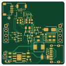
About the Pendant PCB
Pendant is an open source STM32 PCB design by picafe, published on GitHub. It is a 4-layer board measuring 33.2 × 33.2 mm, with 45 components from 31 distinct parts.
Its main chip is the STM32C071G8U6, from the STM32 family. Other key parts include the XC6206P332MR, TPS61022, LIS2DW12TR and TP4056-42-ESOP8. By type, the board carries 13 capacitors, 13 resistors, 5 ICs, 5 connectors, 3 transistors and 3 diodes.
It belongs with the power & battery and displays & leds designs in this gallery.
From the project
A pendant built from two PCBs: a 8×8 bicolor LED matrix module (red, orange, green) and controller board with battery charging, USB-C power, 5 V boost, and motion sensing.
A pendant built from two PCBs: a 8×8 bicolor LED matrix module (red, orange, green) and controller board with battery charging, USB-C power, 5 V boost, and motion sensing.
I had already been working on a 32×8 bicolor matrix module and wanted to try the Pendant YSWS before the deadline. An example on the pendant website inspired me to make a bicolor version with an orange fire-style pattern. Fitting the full matrix and controller on one 2/4 layer board was not the most possible, so my design splits into a display PCB and a pendant controller, which are connected with 2.54mm pitch pin headers…
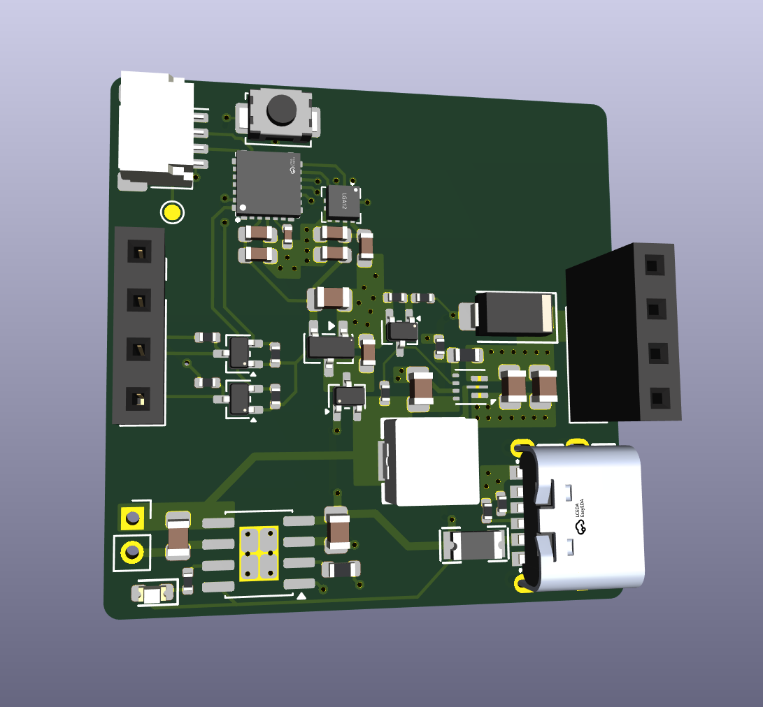
Main components on the Pendant
Pendant bill of materials (BOM)
45 components, 31 distinct parts — part numbers from the project's BOM.
| Qty | Part | Footprint | Refs |
|---|---|---|---|
| 1 | XC6206P332MR Torex Semicon | SOT-23-3 | U1 |
| 1 | STM32C071G8U6 ST(意法半导体) | QFN-28_L4.0-W4.0-P0.50-TL | U3 |
| 1 | TPS61022 | Texas_RWU0007A_VQFN-7_2x2mm_P0.5mm | U4 |
| 1 | LIS2DW12TR ST(意法半导体) | LGA-12_L2.0-W2.0-P0.50-BL | U5 |
| 1 | TP4056-42-ESOP8 | SOIC-8-1EP_3.9x4.9mm_P1.27mm_EP2.41x3.3mm_ThermalVias | U6 |
| 3 | BSS138W hongjiacheng | SOT-323_SC-70 | Q1, Q2, Q3 |
| 1 | CONN_01X04_SOCKET Conn_01x04_Socket | JST_SH_SM04B-SRSS-TB_1x04-1MP_P1.00mm_Horizontal | J1 |
| 2 | CONN_01X04_SOCKET Conn_01x04_Socket | PinSocket_1x04_P2.54mm_Vertical | J2, J3 |
| 1 | USB_C_RECEPTACLE_POWERONLY_6P USB_C_Receptacle_PowerOnly_6P | USB-C-SMD_HX-TYPE-C-6PIN | J4 |
| 1 | CONN_01X02_SOCKET Conn_01x02_Socket | PinSocket_1x02_P2.00mm_Vertical | J5 |
| 1 | SMD1206B150TFT Brightking(君耀电子) | F1206 | F1 |
| 1 | C720477 Tactile Button, 160gf XUNPU | SW_SPST_TS-1088-xR020 | S1 |
| 1 | BAT54CW | SOT-323_SC-70 | D1 |
| 1 | C2286 Red Hubei KENTO Elec | D_0603 | D2 |
| 1 | SS34 MDD(Microdiode Electronics) | D_SMA | D3 |
| 1 | FXL0530-1R0-M cjiang(长江微电) | IND-SMD_L5.4-W5.2_FXL0530 | L1 |
| 1 | 4.7UF 4.7uF Samsung Electro-Mechanics | C_0603 | C1 |
| 1 | 100NF 100nF Samsung Electro-Mechanics | C_0402 | C2 |
| 3 | 100NF 100nF YAGEO | C_0603 | C3, C4, C7 |
| 1 | 1UF 1uF Samsung Electro-Mechanics | C_0603 | C5 |
Show 11 more
| Qty | Part | Footprint | Refs |
|---|---|---|---|
| 1 | 1UF 1uF Samsung Electro-Mechanics | C_0805 | C6 |
| 1 | 10UF 10uF Samsung Electro-Mechanics | C_0603 | C8 |
| 5 | 10UF 10uF Murata Electronics | C_0805 | C9, C10, C11, C12, C13 |
| 1 | 750kΩ UNI-ROYAL(Uniroyal Elec) | R_0603 | R1 |
| 2 | 100kΩ UNI-ROYAL(Uniroyal Elec) | R_0402 | R2, R6 |
| 1 | 1kΩ UNI-ROYAL(Uniroyal Elec) | R_0402 | R3 |
| 2 | 5.1kΩ UNI-ROYAL(Uniroyal Elec) | R_0402 | R4, R5 |
| 1 | 10kΩ UNI-ROYAL(Uniroyal Elec) | R_0603 | R7 |
| 4 | 4.7kΩ UNI-ROYAL(Uniroyal Elec) | R_0402 | R8, R9, R10, R11 |
| 1 | 10kΩ UNI-ROYAL(Uniroyal Elec) | R_0402 | R12 |
| 1 | 120Ω UNI-ROYAL(Uniroyal Elec) | R_0402 | R13 |
Pendant design files
The KiCad project lives in the picafe/pendant repository on GitHub; these links point at the commit this page was built from.
Pendant: common questions
What microcontroller does the Pendant use?
The Pendant is built around the STM32C071G8U6, from the STM32 family.
How big is the Pendant PCB?
The Pendant measures 33.2 × 33.2 mm, has 4 copper layers and is 1.6 mm thick.
How many components are on the Pendant?
45 components, from 31 distinct parts, with part numbers taken from the project's own BOM. The full bill of materials is listed on this page.
Where can I download the Pendant design files?
From the picafe/pendant repository on GitHub, which has the KiCad layout, the schematic and the BOM; the links under Design files point to each one.
Can I use the Pendant design in my own project?
The repository has no license, so all rights stay with picafe. Use it as a reference, and ask the author before reusing the design.
Can I test firmware for the Pendant without the hardware?
Yes. HardLabs builds a simulation of the board from its netlist and BOM, so you can run and debug STM32 firmware against it before you order a PCB.
More boards in pendant
Similar boards
 STM32
STM32LumenPnP Motherboard
opulo-inc
149 × 95 mm296 parts4LCC-BY-SA-4.03.7k STM32
STM32AxxSolder
AxxAxx
39 × 82.5 mm122 parts2LGPL-3.01.7k STM32
STM32AIOC
skuep
21 × 31.5 mm47 parts2LMIT1.4k STM32
STM32Ferris
pierrechevalier83
208.8 × 86.8 mm102 parts2LSHL-2.11.3k STM32
STM32176 pin board
rusefi
61.8 × 73.2 mm76 parts2LGPL-3.01.2k STM32
STM32Brain board STM32F407
61.8 × 73.2 mm69 parts2LGPL-3.01.2k