
Multiprobe

About the Multiprobe PCB
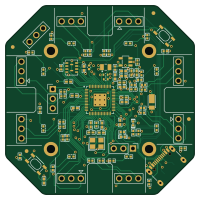
Multiprobe is an open source RP2040/RP2350 PCB design by picolemon, published on GitHub under the MIT license. It is a 4-layer board measuring 50 × 50 mm, with 89 components from 39 distinct parts.
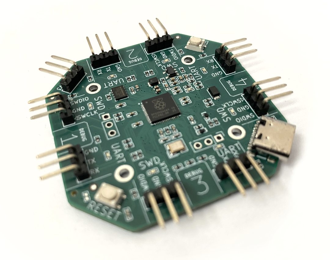
Its main chip is the RP2350A_C42411118, from the RP2040/RP2350 family. Other key parts include the RCLAMP0521P.TCT_C3029033, ME6217C33M5G, W25Q32JVUUIQ and ABM8-272-T3_C20625731. By type, the board carries 36 resistors, 22 capacitors, 11 connectors, 9 LEDs, 6 ICs and 2 switches.
From the project
A debug probe for the RP2050 & RP2035 devices that can debug up to 4 devices at the same time with two active UARTs.
Debug project 1 with UART on COM port ACM0:
Debug project 2 with UART on COM port ACM1:
The UARTs must be assigned to a com port using the table below:
Hint: The vendor code is formatted so the first digit (8 for ACM0 or 9 for ACM1) corresponds to the COM port and the last digit (1,2,3 & 4) is the UART number printed on the board silkscreen.
For example if you plug a device into UART4 and want to communicated on ACM1 you would enter "cmsis-dap cmd 0x94". Some limitation apply due to the pico hardware UART can only be assigned to certain pins, for example UART1 and UART3 can't be used at…
Main components on the Multiprobe
Multiprobe bill of materials (BOM)
89 components, 39 distinct parts — part numbers from the project's BOM.
| Qty | Part | Footprint | Refs |
|---|---|---|---|
| 2 | RCLAMP0521P.TCT_C3029033 RCLAMP0521P.TCT-MS | D0402-BI | U1, U2 |
| 1 | ME6217C33M5G ME6217C33M5G | SOT-23-5_L3.0-W1.7-P0.95-LS2.8-BR | U3 |
| 1 | W25Q32JVUUIQ W25Q32JVUUIQ | USON-8_L4.0-W3.0-P0.80-BL_WINBOND_UU | U4 |
| 1 | ABM8-272-T3_C20625731 | CRYSTAL-SMD_4P-L3.2-W2.5-BL | U5 |
| 1 | RP2350A_C42411118 RP2350A | QFN-60_L7.0-W7.0-P0.40-TL-EP3.4 | U6 |
| 1 | DBG_1 2.54-1*3P正弯针 | HDR-TH_3P-P2.54-H-M-BW7.2-P | J1 |
| 1 | UART_1 2.54-1*3P正弯针 | HDR-TH_3P-P2.54-H-M-BW7.2-P | J2 |
| 1 | DBG_2 2.54-1*3P正弯针 | HDR-TH_3P-P2.54-H-M-BW7.2-P | J3 |
| 1 | UART_2 2.54-1*3P正弯针 | HDR-TH_3P-P2.54-H-M-BW7.2-P | J4 |
| 1 | DBG_3 2.54-1*3P正弯针 | HDR-TH_3P-P2.54-H-M-BW7.2-P | J5 |
| 1 | UART_3 2.54-1*3P正弯针 | HDR-TH_3P-P2.54-H-M-BW7.2-P | J6 |
| 1 | DBG_4 2.54-1*3P正弯针 | HDR-TH_3P-P2.54-H-M-BW7.2-P | J7 |
| 1 | UART_4 2.54-1*3P正弯针 | HDR-TH_3P-P2.54-H-M-BW7.2-P | J8 |
| 1 | DEBUG_UART | PinHeader_1x03_P2.54mm_Vertical | J10 |
| 1 | C92159 PWR_OUT 2.54-1*3P正弯针 | HDR-TH_3P-P2.54-H-M-BW7.2-P | J11 |
| 1 | DEBUG_SWD | PinHeader_1x03_P2.54mm_Vertical | J12 |
| 2 | C92589 ~ K2-1808SN-A4SW | KEY-SMD_4P-L4.2-W3.2-P2.20-LS5.1-TL | SW1, SW2 |
| 1 | TYPE-C-31-M-12 type-c-31-m-12 type-c-31-m-12 | USB-C-SMD_TYPE-C-6PIN-2MD-073 | USB1 |
| 8 | C130723 ~ NCD0402G1 | LED0402-RD | LED1, LED2, LED3, LED4, LED5, LED6, LED7, LED8 |
| 1 | C130719 ~ NCD0402R1 | LED0402-RD | LED9 |
Show 19 more
| Qty | Part | Footprint | Refs |
|---|---|---|---|
| 1 | C110493 D DFLS130L-7 | POWERDI-123_L2.8-W1.8-LS3.7-RD | D1 |
| 1 | AOTA-B201610S3R3-101-T | IND-SMD_L2.0-W1.6_AOTA-B201610S3R3-101-T | L1 |
| 2 | C10UF C10uF GRM155R61A106ME44D | C0402 | C1, C3 |
| 4 | C100NF C100nF GRM155R71H104KE14D | C0402 | C2, C4, C5, C8 |
| 2 | C15PF C15pF | C0402 | C6, C7 |
| 3 | C4.7UF C4.7uF CL05A475KP5NRNC | C_0402_1005Metric | C9, C10, C21 |
| 10 | 100NF 100nf | C0402 | C11, C12, C13, C14, C15, C16, C17, C18 +2 |
| 1 | C4.7UF C4.7uF CL05A475KP5NRNC | C0402 | C20 |
| 1 | R10K RC0402FR-0710KL | R0402 | R1 |
| 2 | R5.1K 0402WGJ0512TCE | R0402 | R2, R6 |
| 1 | R5.6K 0402WGF5601TCE | R0402 | R3 |
| 2 | R27 0402WGF270JTCE | R0402 | R4, R5 |
| 1 | R100K RC0402FR-07100KL | R0402 | R7 |
| 1 | R1K 0402WGJ0102TCE | R0402 | R8 |
| 1 | R10K RC0402FR-0710KL | R0402 | R9 |
| 1 | 1K | R0402 | R10 |
| 1 | R33 RT0402BRD0733RL | R0402 | R11 |
| 9 | R2K 0402WGF2001TCE | R0402 | R12, R14, R15, R16, R17, R18, R19, R20 +1 |
| 16 | R100 0402WGF1000TCE | R0402 | R22, R23, R24, R25, R26, R27, R28, R29 +8 |
Multiprobe design files
The KiCad project lives in the picolemon/multiprobe repository on GitHub; these links point at the commit this page was built from.
Multiprobe: common questions
What microcontroller does the Multiprobe use?
The Multiprobe is built around the RP2350A_C42411118, from the RP2040/RP2350 family.
How big is the Multiprobe PCB?
The Multiprobe measures 50 × 50 mm, has 4 copper layers and is 1.6 mm thick.
How many components are on the Multiprobe?
89 components, from 39 distinct parts, with part numbers taken from the project's own BOM. The full bill of materials is listed on this page.
Where can I download the Multiprobe design files?
From the picolemon/multiprobe repository on GitHub, which has the KiCad layout, the schematic and the BOM; the links under Design files point to each one.
Can I use the Multiprobe design in my own project?
Yes, under the terms of its MIT license, which picolemon chose for the repository.
Can I test firmware for the Multiprobe without the hardware?
Yes. HardLabs builds a simulation of the board from its netlist and BOM, so you can run and debug RP2040/RP2350 firmware against it before you order a PCB.
Similar boards
 RP2040/RP2350
Open Book Abridged Edition
joeycastillo
85 × 115 mm29 parts2LCC-BY-SA-4.08.1k RP2040/RP2350
Corne
foostan
277.2 × 107.5 mm164 parts2LCC-BY-4.07.7k RP2040/RP2350
Corne
277.2 × 107.5 mm164 parts2LCC-BY-4.07.7k RP2040/RP2350
LogicAnalyzer
gusmanb
57 × 55.2 mm6 parts2LGPL-3.05.0k RP2040/RP2350
Jitx design
55.5 × 65 mm26 parts4LGPL-3.05.0k RP2040/RP2350
Main
google
98 × 71 mm102 parts2LApache-2.02.9k