
Panel gauge clock

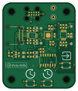
About the Panel gauge clock PCB
Panel gauge clock is an open source PCB design by pilotingpete, published on GitHub. It is a 2-layer board measuring 39.4 × 46.2 mm, with 65 components from 33 distinct parts.
Other key parts include the ADA4891-2, AP2112K-3.3, CH340E, XMC1302 and 74HC14. By type, the board carries 22 resistors, 14 capacitors, 10 diodes, 8 connectors, 5 ICs and 3 switches.
It belongs with the power & battery, sensors and usb & debug tools designs in this gallery.
From the project
From ./Build dir make clean and make all are available.
From ./Build dir make clean and make all are available.
On the XMC1300 boot kit dev board, you can use jflash lite to install the hex file.
Flash with jflash lite [JFlashLite] and seggerjlink ToDo: jlink commander to flash from command line
Assume 50 mA max current. Probably closer to 25 mA
XMC1302-0064 12 mA max current 2-6 mA in sleep mode
500 mV full scale 100 ohm resistance? = 5 mA each, 10 mA total
Main components on the Panel gauge clock
Panel gauge clock bill of materials (BOM)
65 components, 33 distinct parts — part numbers from the project's BOM.
| Qty | Part | Footprint | Refs |
|---|---|---|---|
| 1 | ADA4891-2 | MSOP-8_3x3mm_P0.65mm | U1 |
| 1 | AP2112K-3.3 | SOT-23-5 | U2 |
| 1 | CH340E | MSOP-10_3x3mm_P0.5mm | U3 |
| 1 | XMC1302 | VQFN-24-1EP_4x4mm_P0.5mm_EP2.45x2.45mm | U4 |
| 1 | 74HC14 | SOIC-14_3.9x8.7mm_P1.27mm | U5 |
| 1 | MMBT3904 | SOT-23 | Q1 |
| 1 | USB_C_RECEPTACLE_USB2.0 USB_C_Receptacle_USB2.0 | USB_C_Receptacle_Amphenol_12401610E4-2A_CircularHoles | J1 |
| 7 | CONN_01X02 Conn_01x02 | JST_ACH_BBM02B-ACHSS-GAN-ETF_1x02-1MP_P1.20mm_Vertical | J3, J4, J5, J6, J7, J8, J9 |
| 3 | SW_PUSH | SW_SPST_PTS810 | SW1, SW2, SW3 |
| 2 | TestPoint | TestPoint_Loop_D1.80mm_Drill1.0mm_Beaded | TP9, TP10 |
| 1 | BLUE - LB Q39G-L2OO-35-1 | LED_0603_1608Metric | D1 |
| 1 | GREEN - LT Q39G-Q1OO-25-1 | LED_0603_1608Metric | D2 |
| 5 | BAT760 | D_SOD-323 | D3, D4, D8, D9, D10 |
| 1 | MCU_LED | LED_0603_1608Metric | D5 |
| 2 | WHITE - LW Q38G-Q1OO-3K6L-1 | LED_0603_1608Metric | D6, D7 |
| 1 | 1µF, 10V | C_0603_1608Metric | C1 |
| 2 | 4.7µF, 6.3V | C_0603_1608Metric | C2, C3 |
| 1 | 0.1µF, 6.3V x7r | C_0603_1608Metric | C4 |
| 5 | 1µF, 6.3V | C_0603_1608Metric | C5, C11, C12, C13, C14 |
| 2 | 0.1µF, 6.3V | C_0603_1608Metric | C6, C10 |
Show 13 more
| Qty | Part | Footprint | Refs |
|---|---|---|---|
| 1 | 10µF, 10V tant | CP_EIA-1608-08_AVX-J | C7 |
| 1 | 0.01µF, 6.3V | C_0603_1608Metric | C8 |
| 1 | 220nF, 6.3V | C_0603_1608Metric | C9 |
| 2 | 15K0 15k0 | R_0603_1608Metric | R1, R2 |
| 3 | 4K3 4k3 | R_0603_1608Metric | R3, R4, R12 |
| 2 | 5K1 5k1 | R_0603_1608Metric | R5, R6 |
| 2 | 1K0 1k0 | R_0603_1608Metric | R7, R8 |
| 3 | 10K0 10k0 | R_0603_1608Metric | R9, R10, R13 |
| 1 | 220R | R_0603_1608Metric | R11 |
| 1 | 100K0 100k0 | R_0603_1608Metric | R14 |
| 1 | 56R | R_0805_2012Metric | R15 |
| 1 | 910R | R_0603_1608Metric | R16 |
| 6 | 22K 22k | R_0603_1608Metric | R17, R18, R19, R20, R21, R22 |
Panel gauge clock design files
The KiCad project lives in the pilotingpete/panel-gauge-clock repository on GitHub; these links point at the commit this page was built from.
Panel gauge clock: common questions
How big is the Panel gauge clock PCB?
The Panel gauge clock measures 39.4 × 46.2 mm, has 2 copper layers and is 1.6 mm thick.
How many components are on the Panel gauge clock?
65 components, from 33 distinct parts, with part numbers taken from the project's own BOM. The full bill of materials is listed on this page.
Where can I download the Panel gauge clock design files?
From the pilotingpete/panel-gauge-clock repository on GitHub, which has the KiCad layout, the schematic and the BOM; the links under Design files point to each one.
Can I use the Panel gauge clock design in my own project?
The repository has no license, so all rights stay with pilotingpete. Use it as a reference, and ask the author before reusing the design.
Similar boards
Sensor smd
scottbez1
40 × 20 mm5 parts2LApache-2.04.2k
Sensors
StuckAtPrototype
15.2 × 9 mm14 parts4LApache-2.03.8k
EinkPDA screen
TalismanDesign
95 × 54 mm27 parts2LApache-2.02.0k
Stack chan
stack-chan
50 × 50 mm33 parts2LApache-2.01.7k
Display Carrier
AxxAxx
35.6 × 58.2 mm5 parts2LGPL-3.01.7k
Microphone
Mentra-Community
5.5 × 6.1 mm6 parts2LMIT1.2k