
Phloppy 0

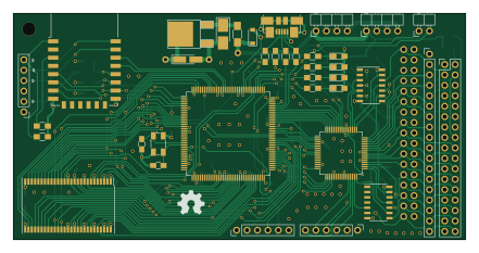
About the Phloppy 0 PCB
Phloppy 0 is an open source ESP8266 PCB design by piotr-wiszowaty, published on GitHub under the GPL-3.0 license. It is a 4-layer board measuring 110 × 55 mm, with 83 components from 39 distinct parts.
Its main chip is the ESP-12E, from the ESP8266 family. Other key parts include the LM1117-3.3, STM32F446ZCTx, AS4C4M16SA, XC9572XL-VQ64 and 74LCX07. By type, the board carries 33 capacitors, 27 resistors, 10 connectors, 7 ICs, 4 LEDs and 1 crystal.
It belongs with the retro computing and iot & wireless designs in this gallery.
From the project
Commodore Amiga floppy drive emulator
phloppy\0 is a Commodore Amiga floppy drive emulator. It emulates four drives (DF0:, DF1:, DF2:, DF3:`) and is controlled through WiFi by an Android or a PC application.
DF0: - DF3: interoperation --------------------------
The device is connected between the Amiga motherboard and the internal floppy drive (DF0:). When a floppy image is inserted in the virtual DF0: the physical drive input signals SEL0 and MTR0 are inactive. When there is no floppy image in the virtual DF0: the SEL0 and MTR0 signals are passed from the Amiga motherboard through the emulator to the physical drive.
Main components on the Phloppy 0
Phloppy 0 bill of materials (BOM)
83 components, 39 distinct parts.
| Qty | Part | Footprint | Refs |
|---|---|---|---|
| 1 | LM1117-3.3 | TO-252-2Lead | U1 |
| 1 | STM32F446ZCTx | LQFP-144_20x20mm_Pitch0.5mm | U2 |
| 1 | ESP-12E | ESP-12E | U3 |
| 1 | AS4C4M16SA | TSOP-II-54_22.22x10.16mm_Pitch0.8mm | U4 |
| 1 | XC9572XL-VQ64 | TQFP-64_10x10mm_Pitch0.5mm | U5 |
| 2 | 74LCX07 | SOIC-14_3.9x8.7mm_Pitch1.27mm | U6, U7 |
| 1 | ABM3B 8MHz | Crystal_SMD_Abracon_ABM3B-4pin_5.0x3.2mm | Y1 |
| 1 | USB_OTG | USB_Micro-B_Molex_47346-0001 | J1 |
| 1 | Conn_01x02 | Pin_Header_Angled_1x02_Pitch2.54mm | J2 |
| 1 | PWR_IN | Pin_Header_Angled_1x04_Pitch2.54mm | P1 |
| 1 | PWR_OUT | Pin_Header_Angled_1x04_Pitch2.54mm | P2 |
| 1 | ESP_UART | Pin_Header_Straight_1x06_Pitch2.54mm | P3 |
| 1 | SWD | Pin_Header_Straight_1x06_Pitch2.54mm | P4 |
| 1 | JTAG | Pin_Header_Straight_1x06_Pitch2.54mm | P5 |
| 1 | TEST | Pin_Header_Straight_1x18_Pitch2.54mm | P6 |
| 1 | Floppy | Pin_Header_Straight_2x17_Pitch2.54mm | P7 |
| 1 | Amiga | Pin_Header_Straight_2x17_Pitch2.54mm | P8 |
| 1 | YELLOW | LED_0805_HandSoldering | LED1 |
| 1 | GREEN | LED_0805_HandSoldering | LED2 |
| 1 | BLUE | LED_0805_HandSoldering | LED3 |
Show 19 more
| Qty | Part | Footprint | Refs |
|---|---|---|---|
| 1 | RED | LED_0805_HandSoldering | LED4 |
| 1 | 1N5819 | D_SOD-123 | D1 |
| 2 | 10 pF | C_0805_HandSoldering | C1, C7 |
| 27 | 100 nF | C_0805_HandSoldering | C2, C3, C4, C5, C8, C9, C10, C11 +19 |
| 1 | 10uF | CP_Tantalum_Case-B_EIA-3528-21_Hand | C6 |
| 1 | 2.2 uF | C_1206_HandSoldering | C14 |
| 1 | 10uF | Tantalum_Case-A_EIA-3216-18_Hand | C18 |
| 1 | 4.7 uF | C_1206_HandSoldering | C31 |
| 1 | 220m | R_1206_HandSoldering | R1 |
| 1 | 5.6k | R_0805_HandSoldering | R2 |
| 6 | 10k | R_0805_HandSoldering | R3, R4, R9, R11, R23, R25 |
| 1 | 100k | R_0805_HandSoldering | R5 |
| 1 | 1.5k | R_0805_HandSoldering | R6 |
| 2 | 0 | R_0805_HandSoldering | R7, R8 |
| 2 | 100 | R_0805_HandSoldering | R10, R24 |
| 9 | 1k | R_0805_HandSoldering | R12, R13, R14, R15, R16, R19, R20, R21 +1 |
| 1 | 330 | R_0805_HandSoldering | R17 |
| 1 | 2.2k | R_0805_HandSoldering | R18 |
| 2 | 100k | R_0805_2012Metric_Pad1.15x1.50mm_HandSolder | R26, R27 |
Phloppy 0 design files
The KiCad project lives in the piotr-wiszowaty/phloppy_0 repository on GitHub; these links point at the commit this page was built from.
- Layoutpcb/phloppy_0.kicad_pcb
Phloppy 0: common questions
What microcontroller does the Phloppy 0 use?
The Phloppy 0 is built around the ESP-12E, from the ESP8266 family.
How big is the Phloppy 0 PCB?
The Phloppy 0 measures 110 × 55 mm, has 4 copper layers and is 1.6 mm thick.
How many components are on the Phloppy 0?
83 components, from 39 distinct parts. The full bill of materials is listed on this page.
Where can I download the Phloppy 0 design files?
From the piotr-wiszowaty/phloppy_0 repository on GitHub, which has the KiCad layout; the links under Design files point to each one.
Can I use the Phloppy 0 design in my own project?
Yes, under the terms of its GPL-3.0 license, which piotr-wiszowaty chose for the repository.
Can I test firmware for the Phloppy 0 without the hardware?
Yes. HardLabs builds a simulation of the board from its netlist and BOM, so you can run and debug ESP8266 firmware against it before you order a PCB.
Similar boards
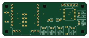 ESP8266
ESP8266ControllerCircuit
stuartpittaway
75 × 30 mm20 parts2LCC-BY-NC-4.01.1k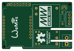 ESP8266
HASwitchPlate
aderusha
60 × 40 mm8 parts2LMIT738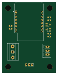 ESP8266
RatGDO-OpenSource-D1Mini-ESP8266
Kaldek
47.8 × 63.3 mm12 parts2LMIT506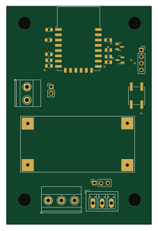 ESP8266
RatGDO-OpenSource-Bare-ESP8266
55 × 82.7 mm20 parts2LMIT506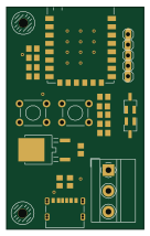 ESP8266
Goatgdo
32.9 × 53.3 mm23 parts2LMIT506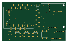 ESP8266
Iaq board
nkitanov
70.1 × 43.2 mm17 parts2LNo license398